Begin by printing the parts included in the ROD PUPPET parts archive. There is a README text file included in the archive in which you'll find required/recommended print settings and also how many you'll need to print of each part.
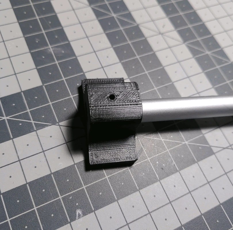
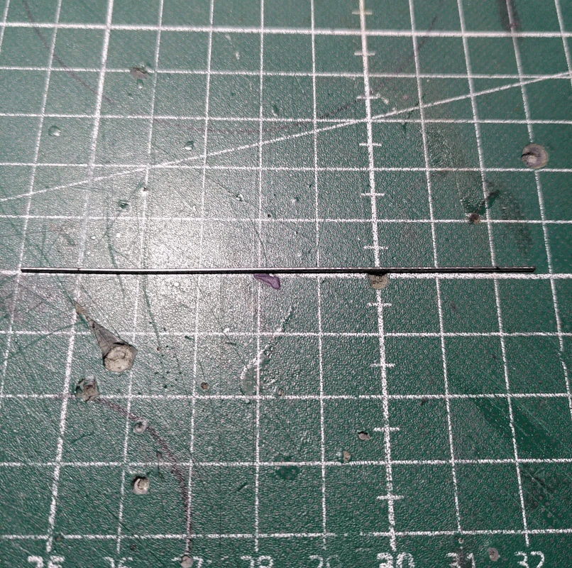
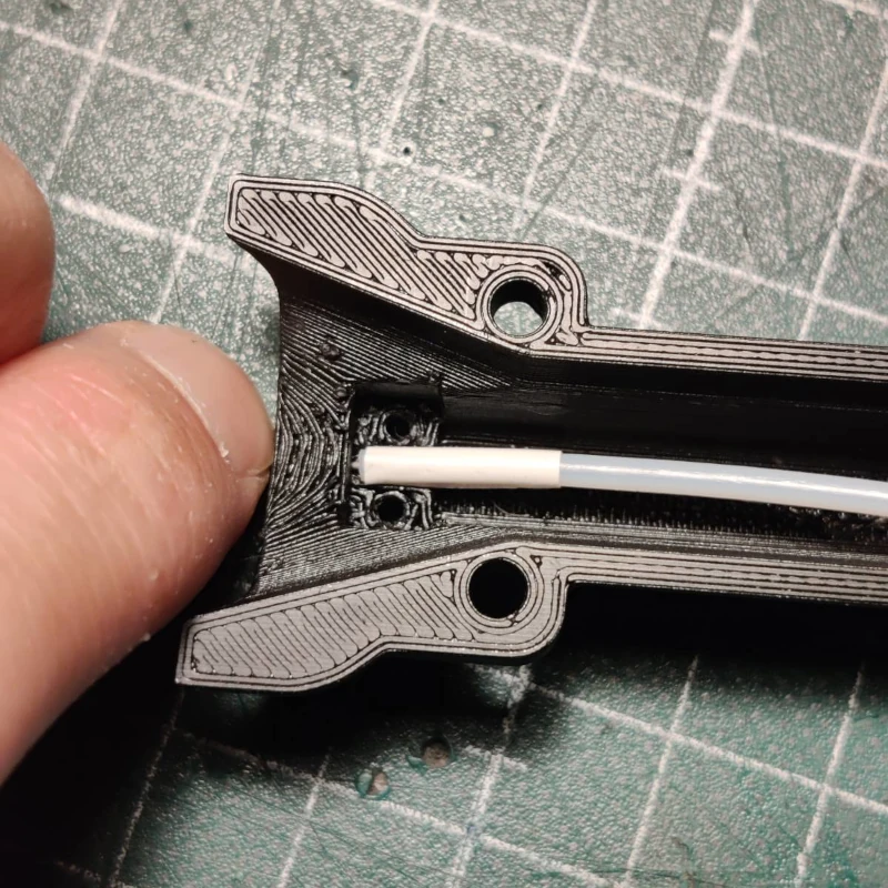
Cut the aluminum rod to a length of 55cm and insert one end into the part labelled
drillhelp_1. Drill a 2mm hole through the rod using the
drillhelp_1 as a guide.
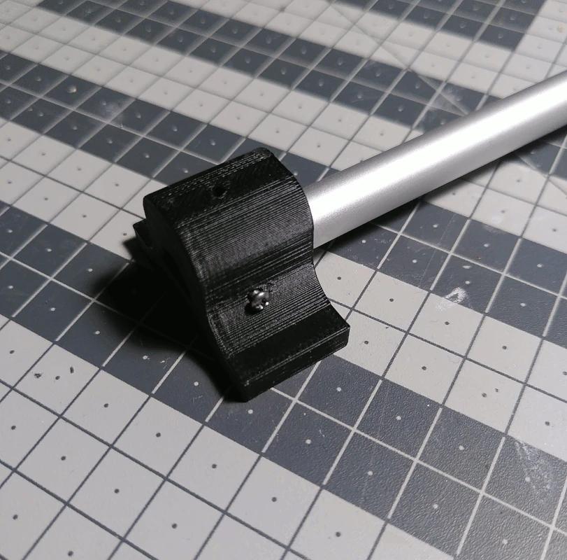
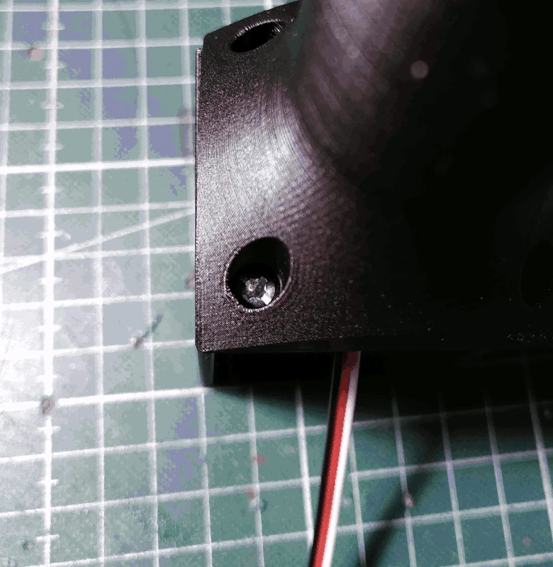
After drilling the hole, turn the rod 90 degrees and fasten it to the
drillhelp_1 using an M2x19mm screw as depicted below.
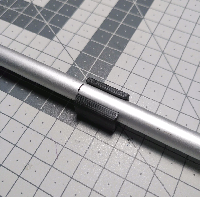
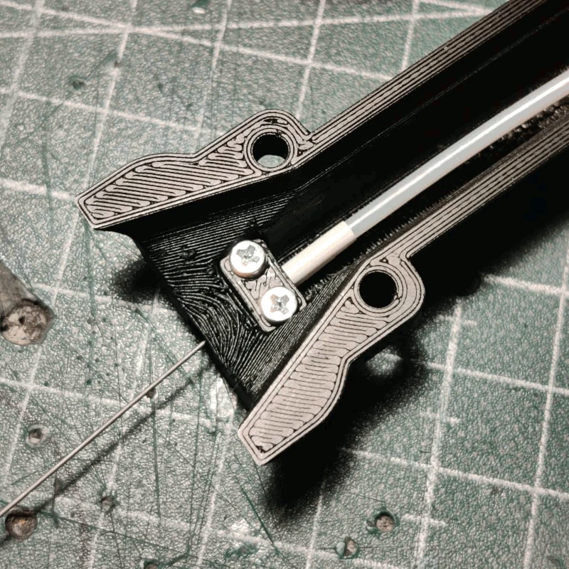
Make a mark 23.5cm in, measuring from the end of the rod that is
not attached to the
drillbit_1, and slide on the part labelled
holehelp unto the rod and place it below the mark as depicted below.
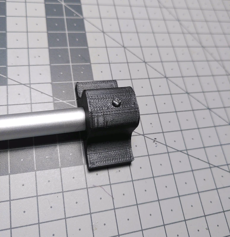
Attach another
drillbit_1 unto the end of the rod (from which you measured previously) and drill another 2mm hole in the same way as before. After drilling, fasten the
drillbit_1 using a M2x19mm screw in the top hole as depicted below.
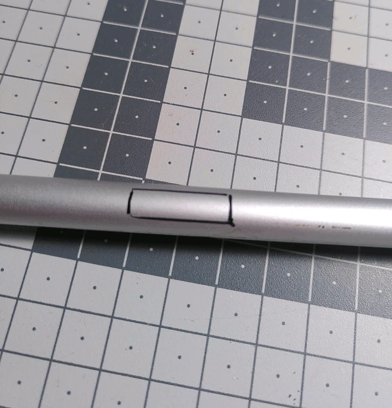
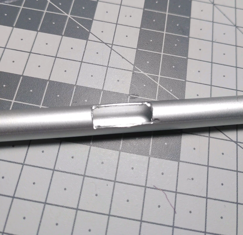
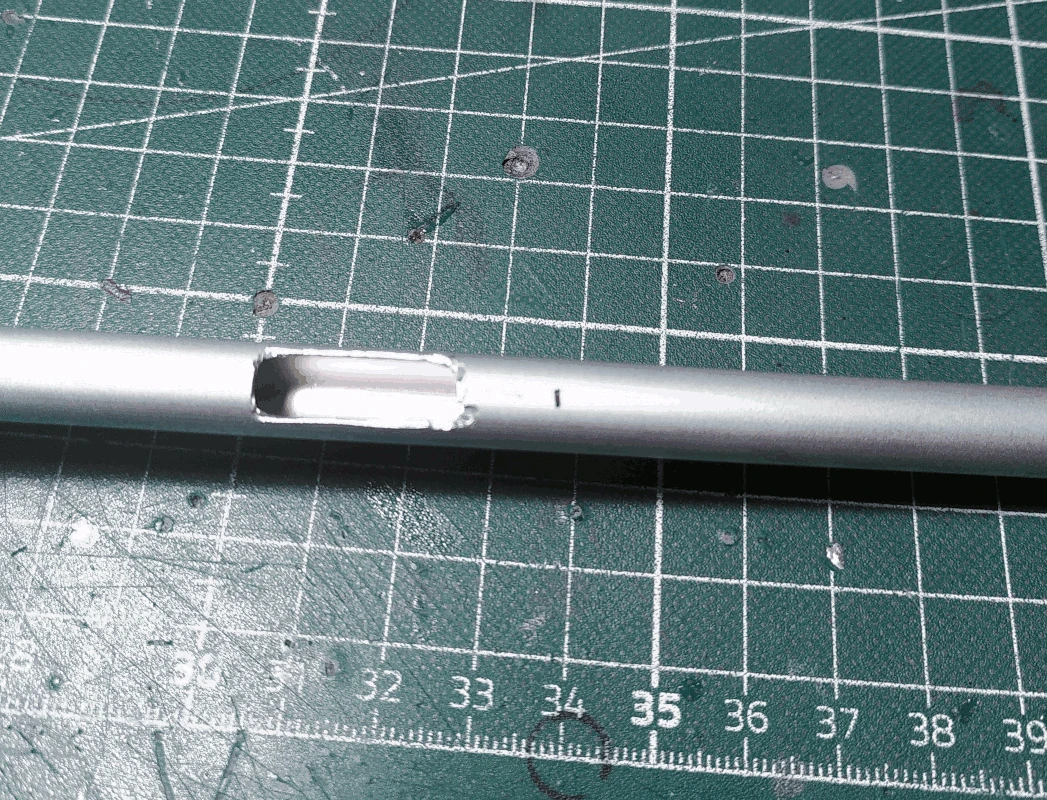
Using the
holehelp as a guide, placed below the mark as previously shown, mark out a square.
Cut out a hole using a cutting tool such as a Dremel. The side of the rod with this hole will from now on be referenced as the front of the rod.
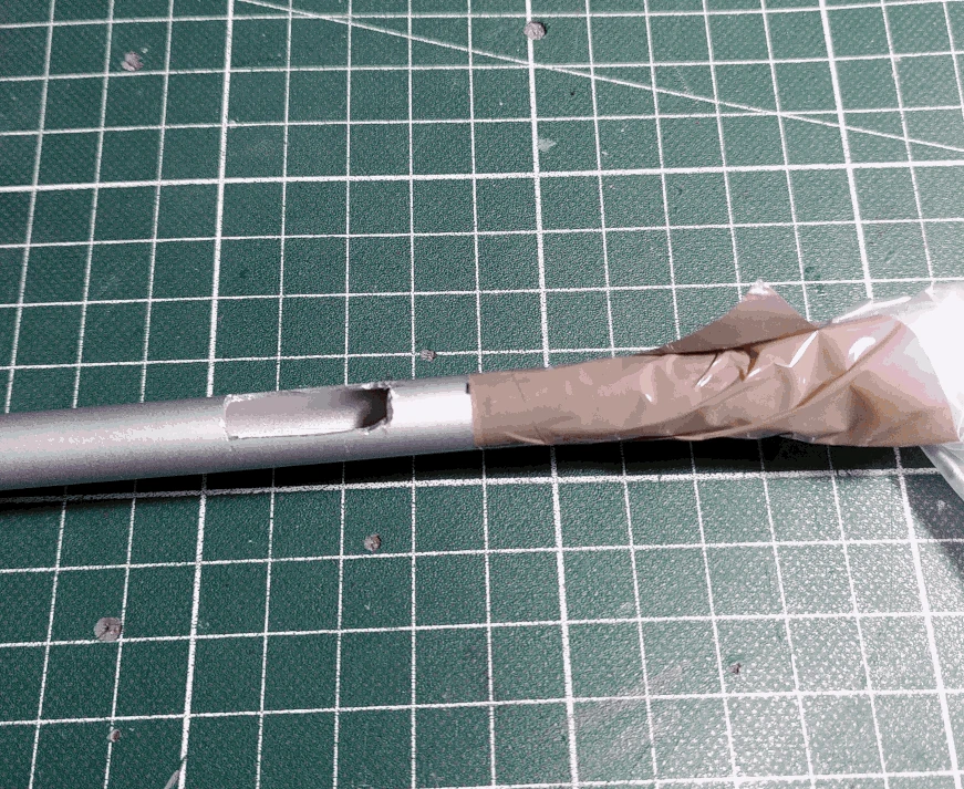
Make another mark about 1cm below the hole (20.5cm measuring from the same end of the rod as before).
Mask the rod from below the mark using something like tape and some plastic or similar.
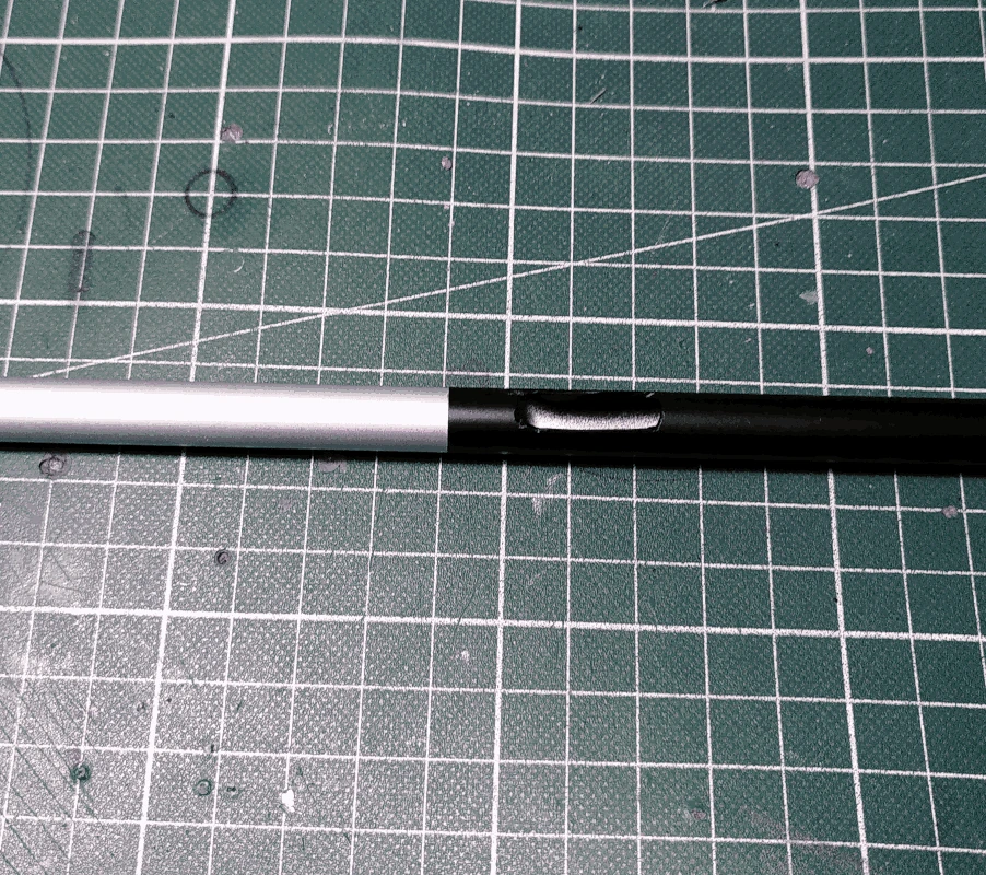
Spray the whole thing black (or whichever color you want it to be). Depending on how well your paint adheres to aluminium it might be necessary to use a primer and a coat of varnish afterwards is recommended.
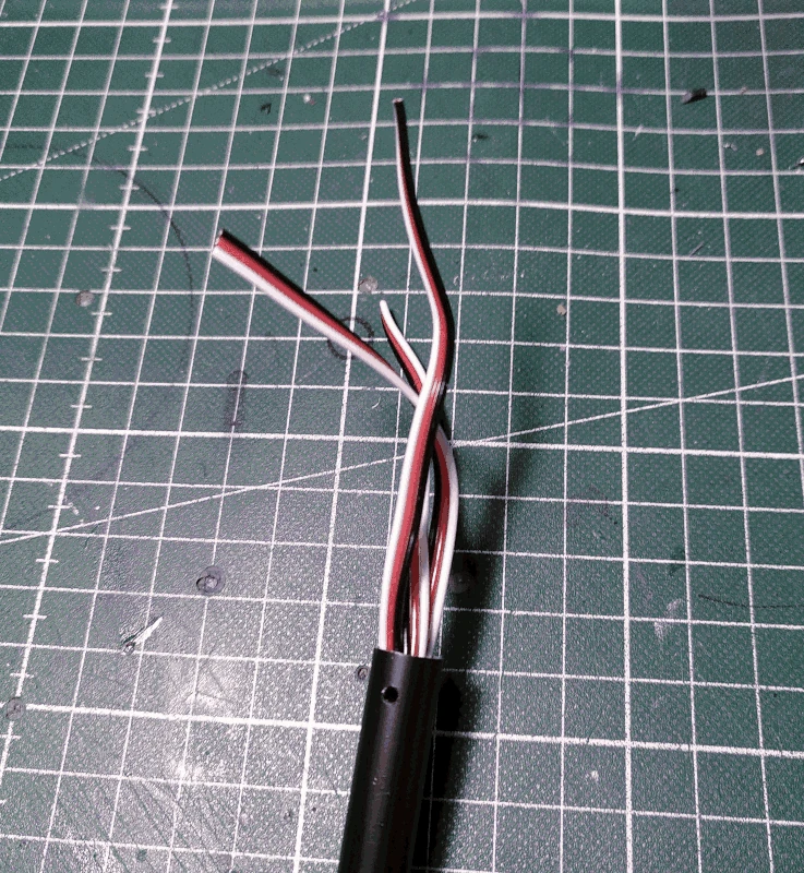
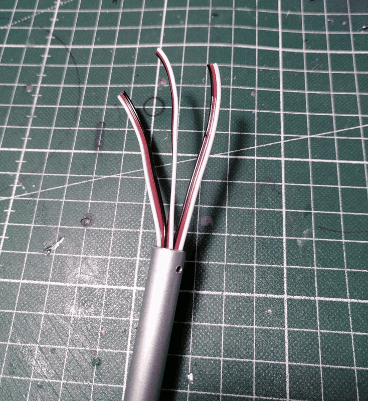
Insert 3 3x1 servo cables of about 70cm into the rod so that the ends protrude about 10cm from each end.
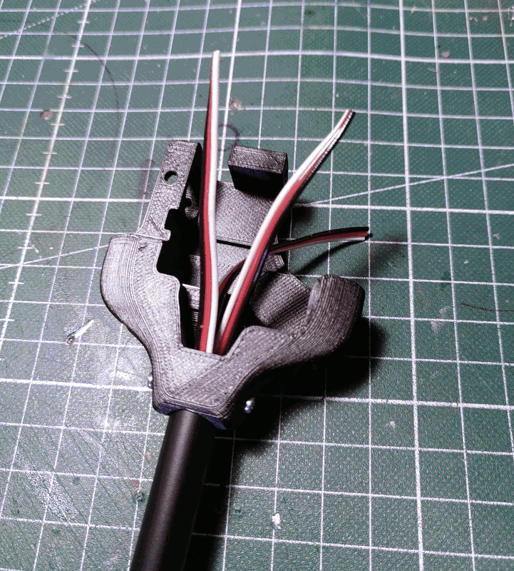
Mount the part labelled
hip to the rod, on the end which is painted, using 2 M2x6mm screws on each side. The front of the rod should be facing the same direction as the side of the
hip that is facing downward in the image below.
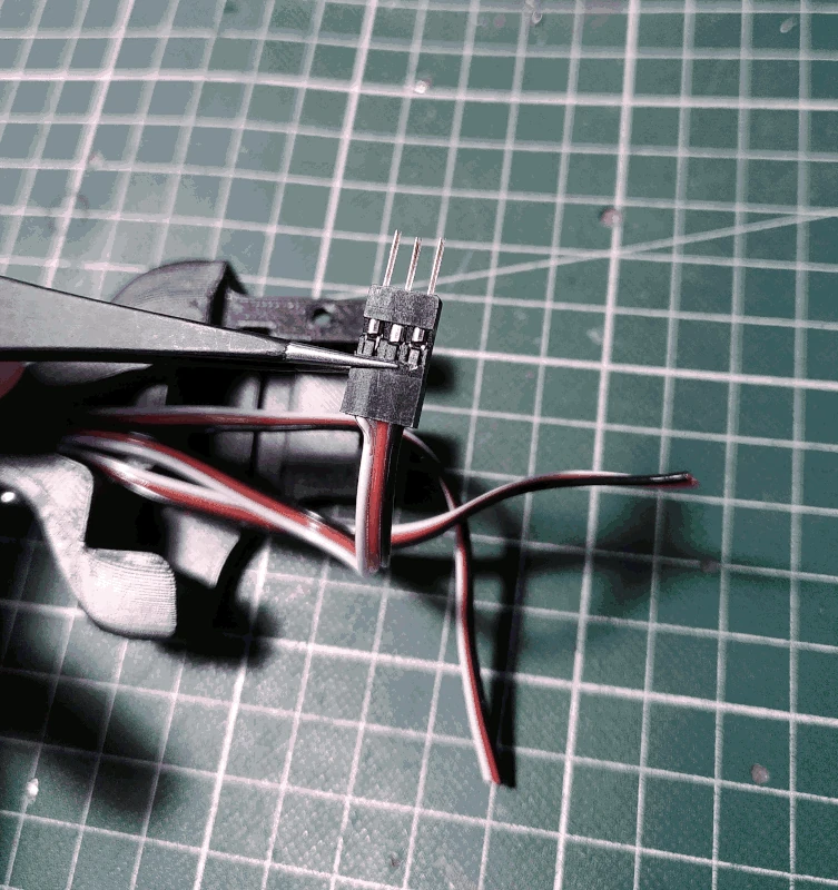
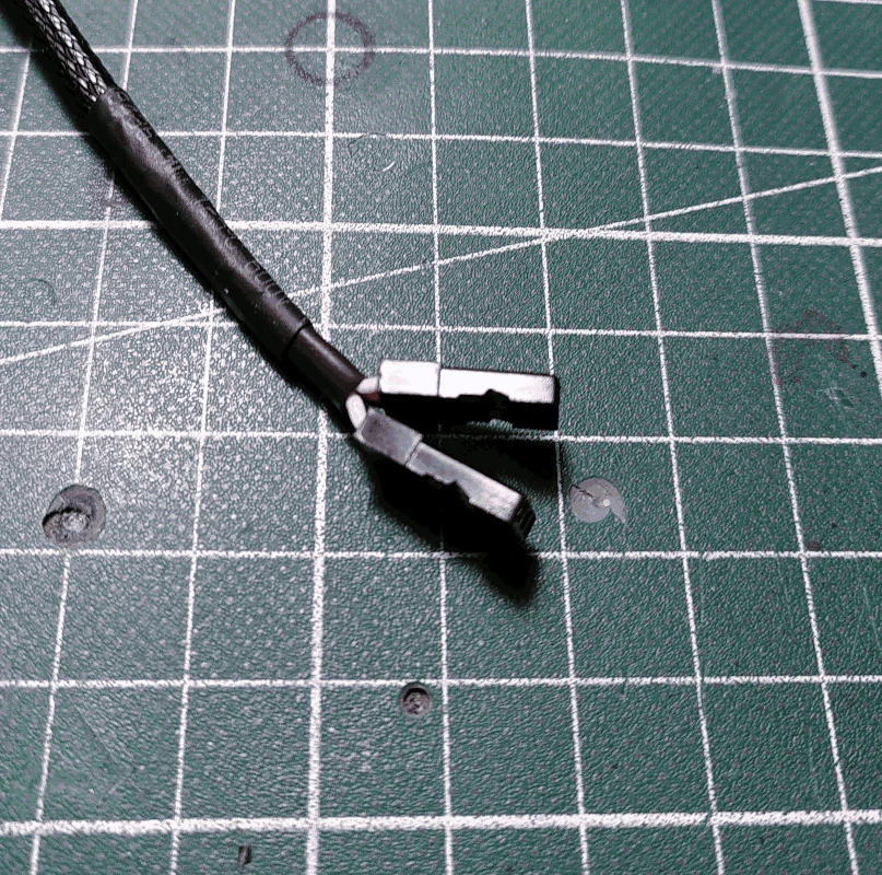
Attach male pins and 3x1 Dupont housing to the ends of the cables.
If you're using sleeves such as the one depicted below and you're unsure which cable to crimp unto which pin, just match the orientation on the connector of a servo. The polarity will be correct when the sleeve is attached and it's easier later on if you follow the polarity of the servo connector.
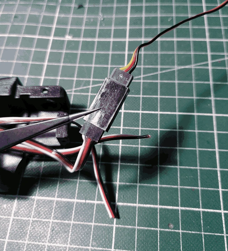
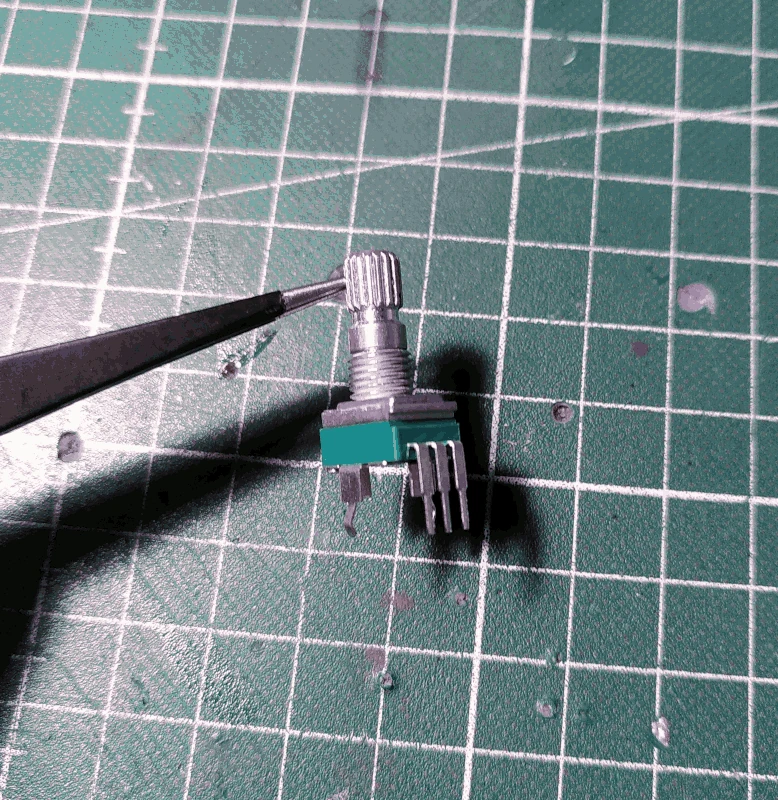
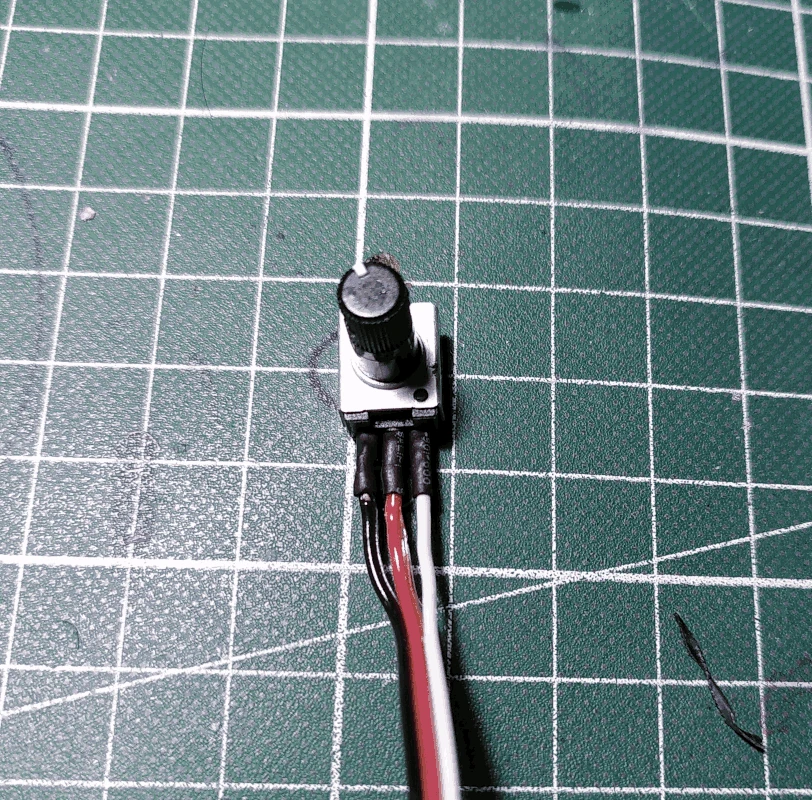
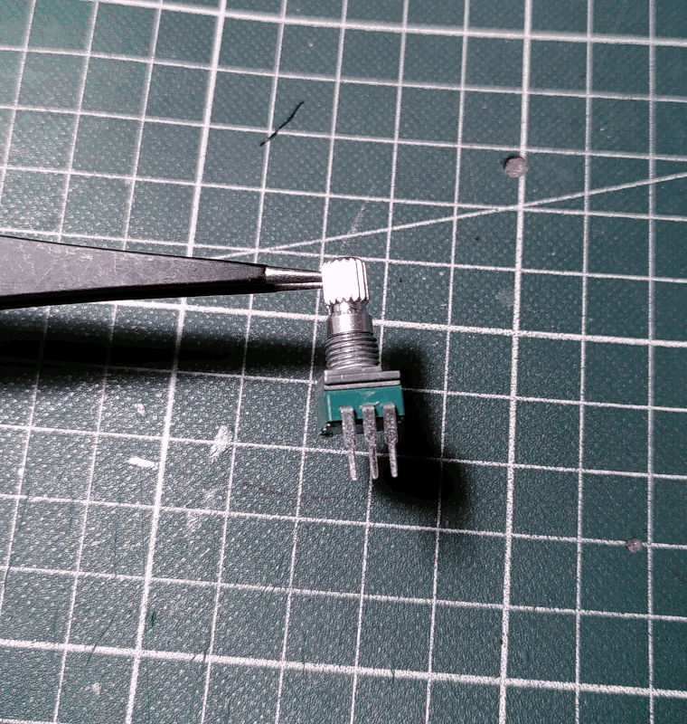
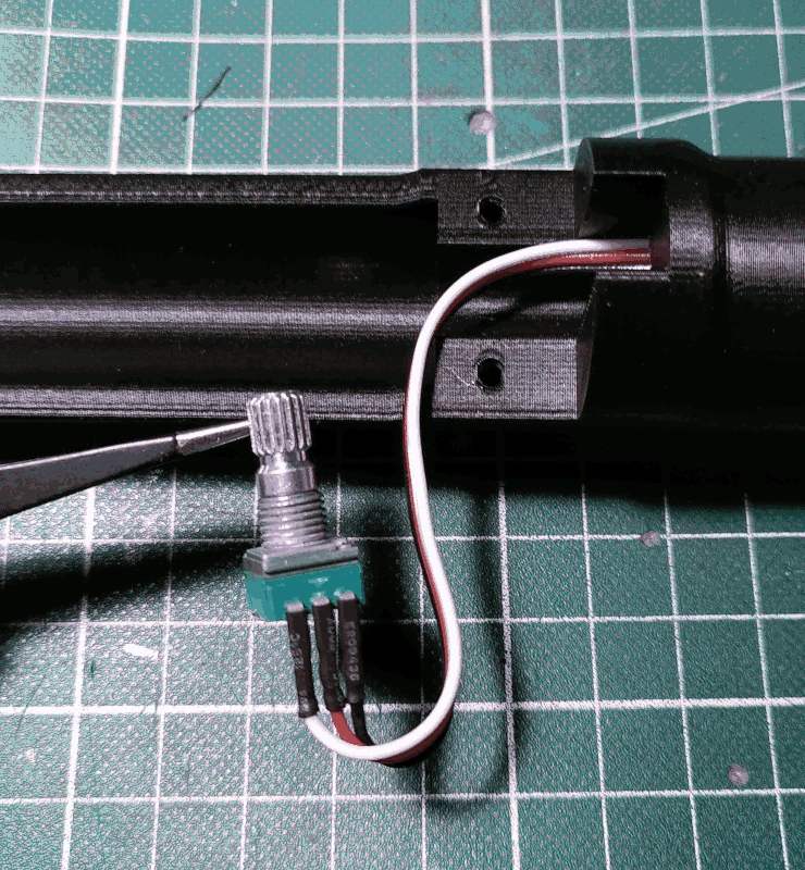
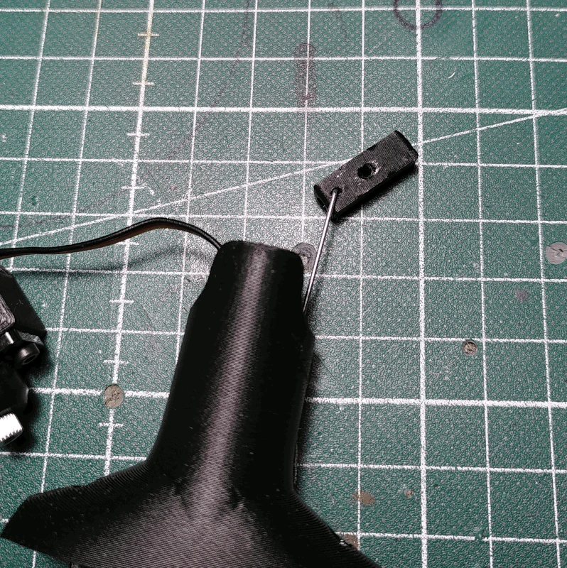
Grab one of the 10Kohm potentiometers with a metal shaft and strip all but the necessary 3 pins and bend them so they're pointing straight out.
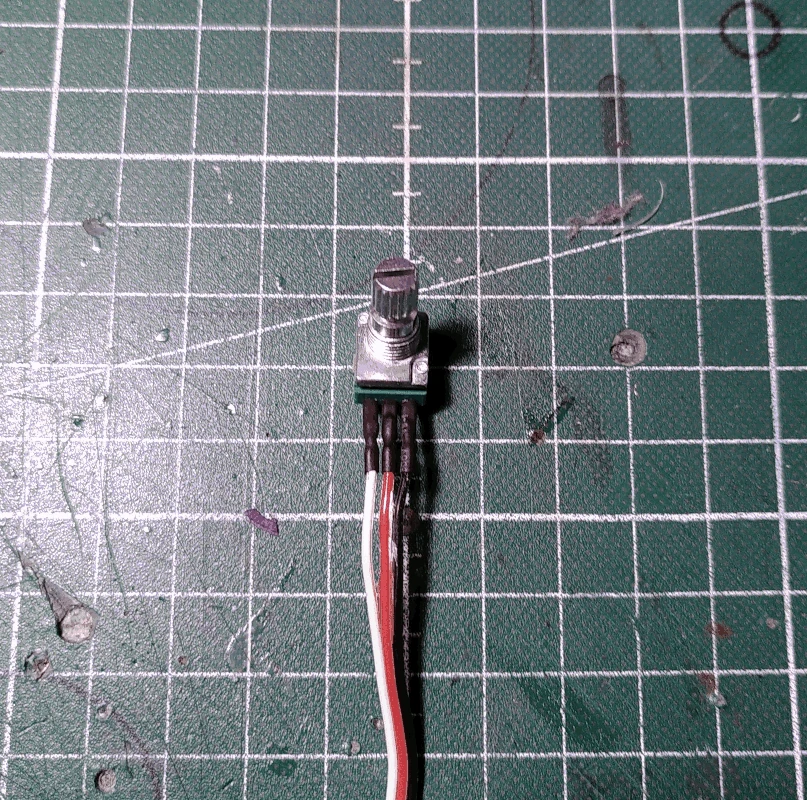
Solder wires to the pins, around 30cm in length. Preferrably 3x1 servo cables (easier to manage). In the image below the right most pin will be GND (black wire). It's a good idea to protect the connections with some heat shrink tubing.
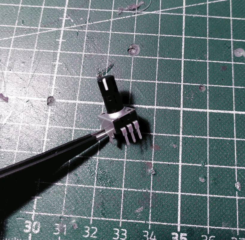
Grab the 10Kohm potentiometer with a plastic shaft and strip all but the necessary 3 pins and bend them so they're pointing outwards. It's a good idea to shorten the remaining 3 pins as well.
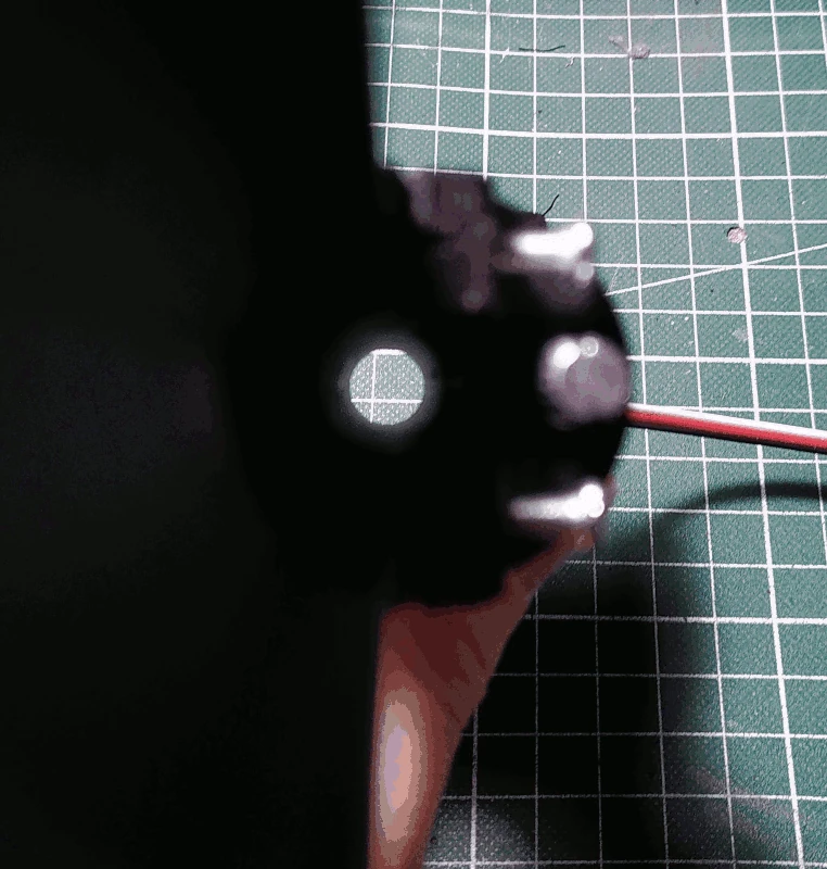
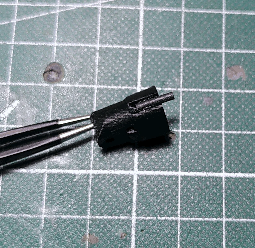
Set the shaft to its middle position and insert it into the part labelled
drillhelp_2. Orientation depicted below. There's a small ridge on the
drillhelp_2 that can be used to verify that the shaft is in its middle position.
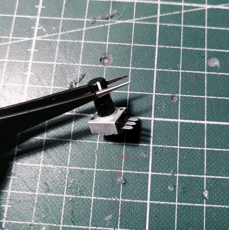
Proceed with drilling a 2mm hole in the shaft, using the
drillhelp_2 as a guide (similar to what was done before with the rod).
After having drilled the hole, solder wires of about 30cm in length to the pins. In the image below the left most pin (black wire) will be GND.
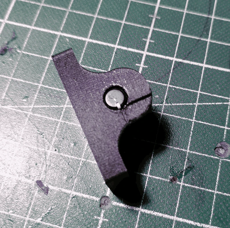
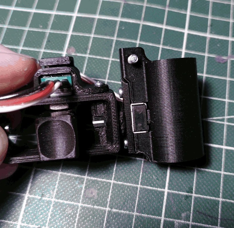
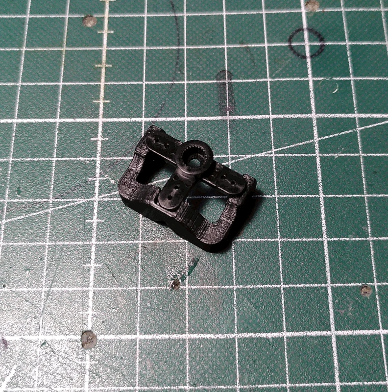
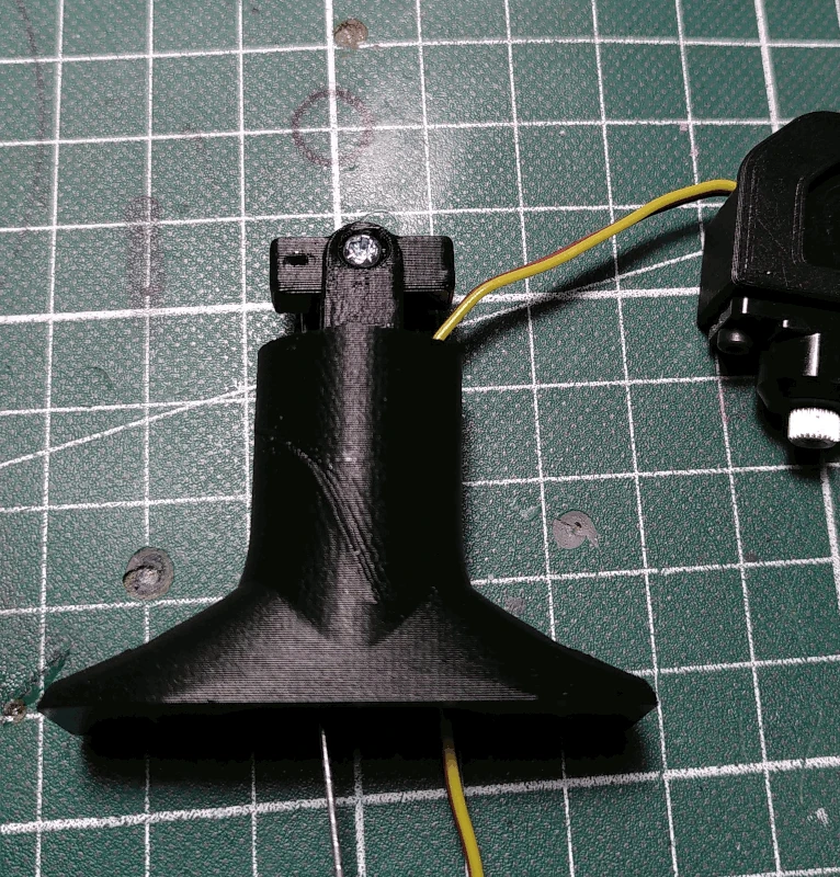
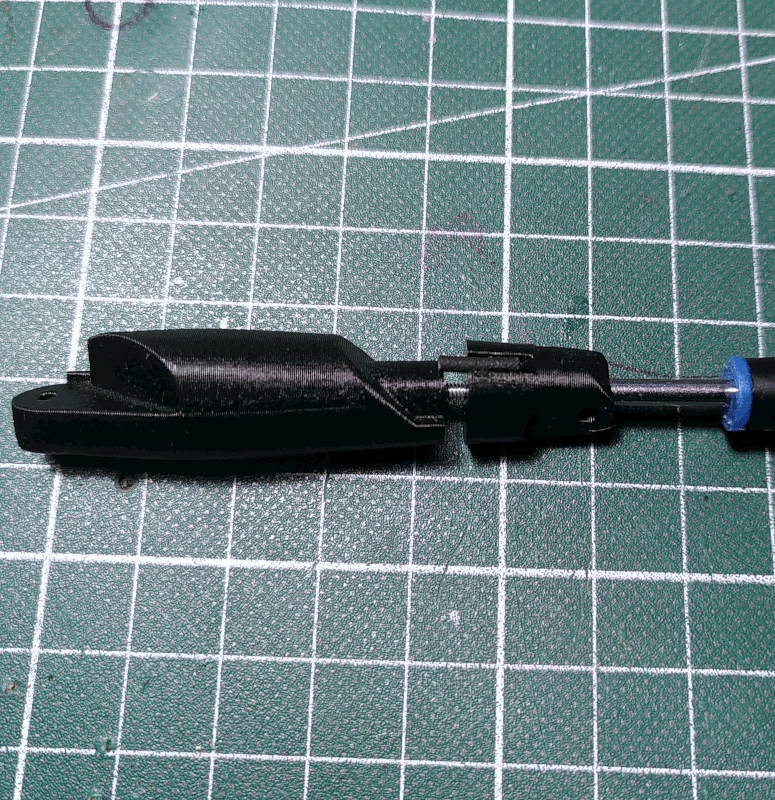
Insert the potentiometer with the plastic shaft into the part labelled
bearing as depicted below. Fasten a M3x12mm screw into the mounting hole at the top of the
bearing with a washer in between (head and washer to the left side, as depicted below).
Attach the part labelled
bearing_lid to the
bearing using 2 M2x6mm screws. If the
bearing_lid is bulging too much you'll have to do a better job of stripping all but the necessary 3 pins from the potentiometer before attaching the
bearing_lid.
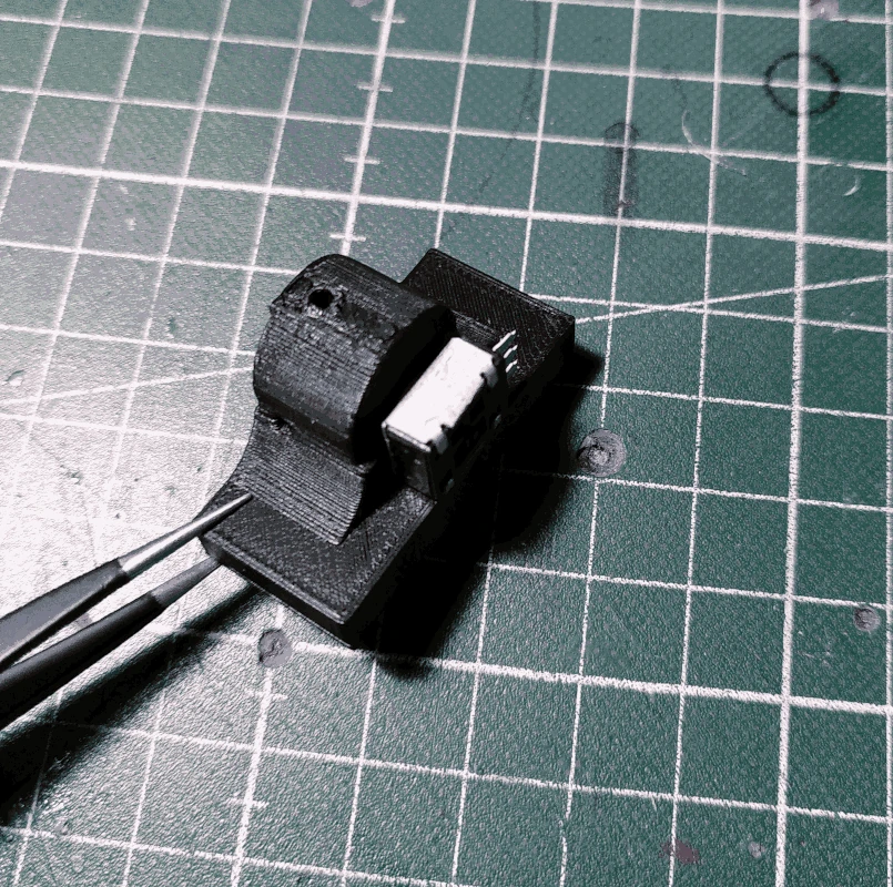
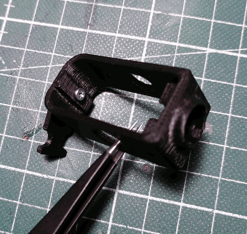
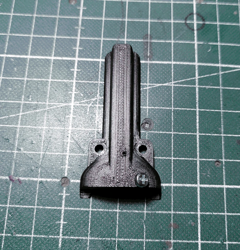
Grab the part labelled
bridge and fasten the part labelled
cable_holder to it using a M2x6mm screw as depicted below. It should be tightened just enough so that the
cable_holder can spin freely.
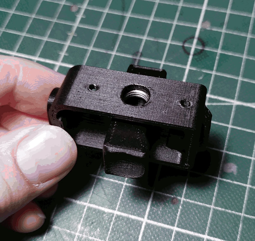
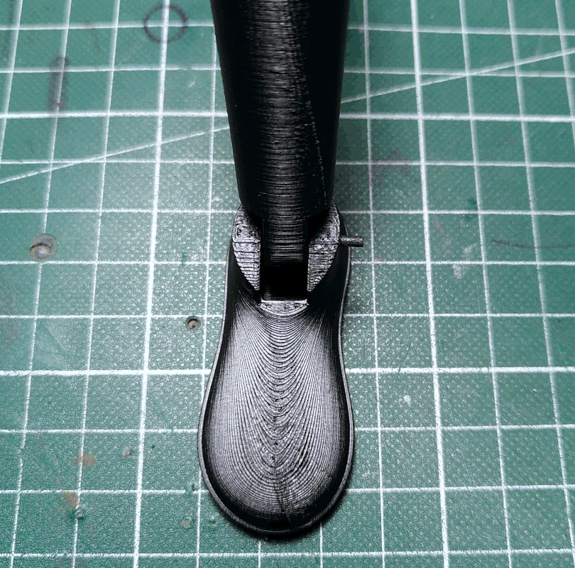
Grab the part labelled
finger_handle and place it upside down into the larger of the holes on the
bridge with the flatter side facing the
cable_holder. Slide a nut for a potentiometer in between the top of the
finger_handle and the
bridge and align it with the top hole.
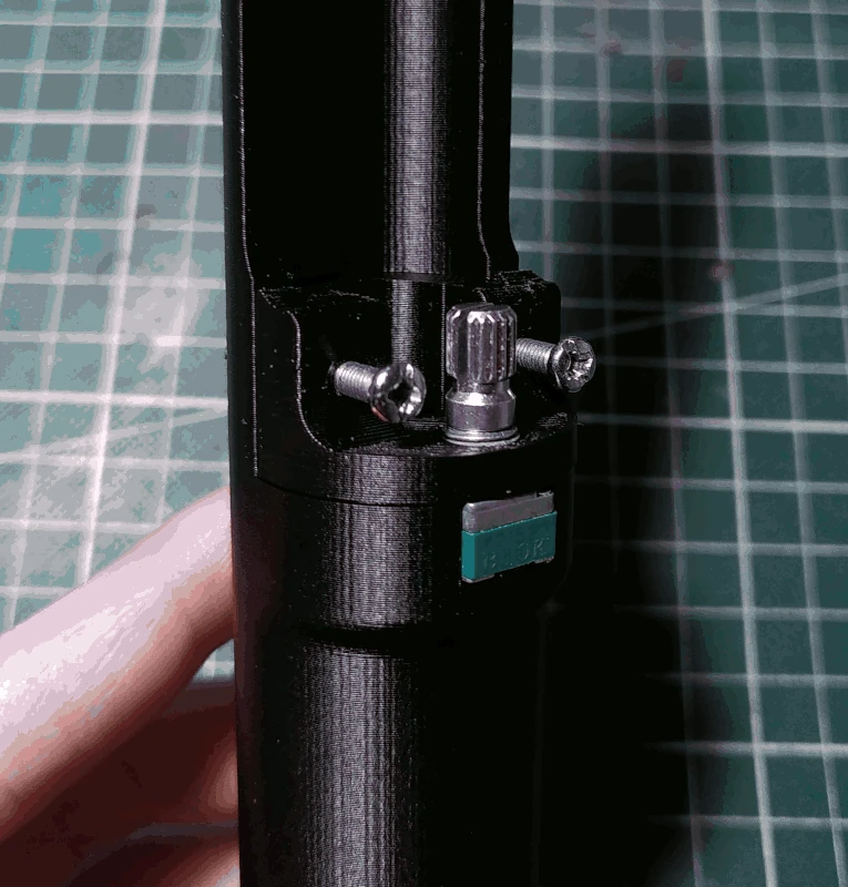
Insert the potentiometer with a metal shaft (that you previously soldered wires to) into the top hole of the
bridge and make sure it fits into the
finger_handle in such a way so that when you tighten the nut the potentiometer is flush against the surface of the
bridge without the
bridge bending. The
finger_bridge has a thin wall across its mounting hole that fits into the ridge of the potentiometer shaft so it can't really be placed in any other orientation than what can be observed in the image below.
Attach the part labelled
cable_clip unto the
bridge by fastening a M2x6mm screw in the mounting hole closest to the
cable_holder.
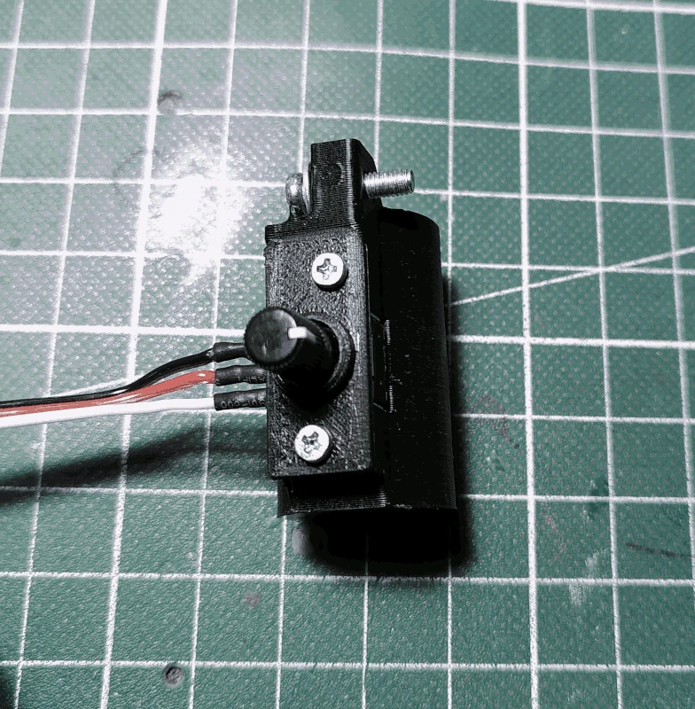
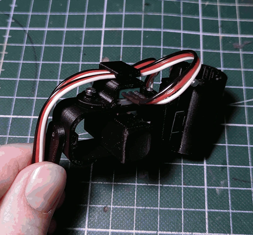
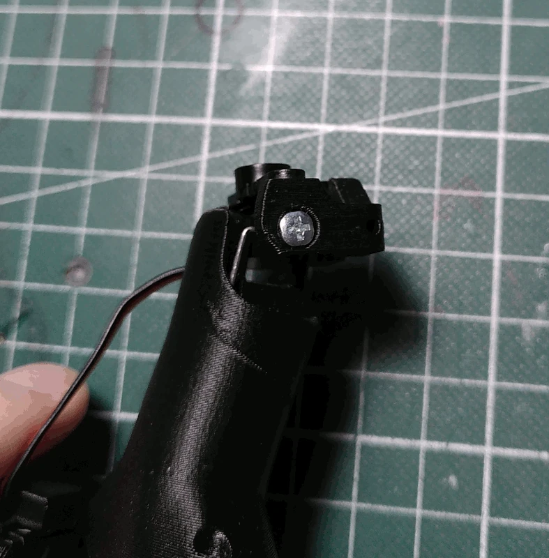
Attach the
bridge to the
bearing but make sure the shaft of the potentiometer is turned to its middle position. Secure the whole thing by fastening a M2x19mm screw through the
cable_clip and
bridge. Double check so that the
bridge can turn smoothly from side to side.
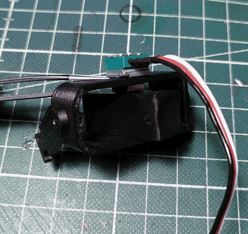
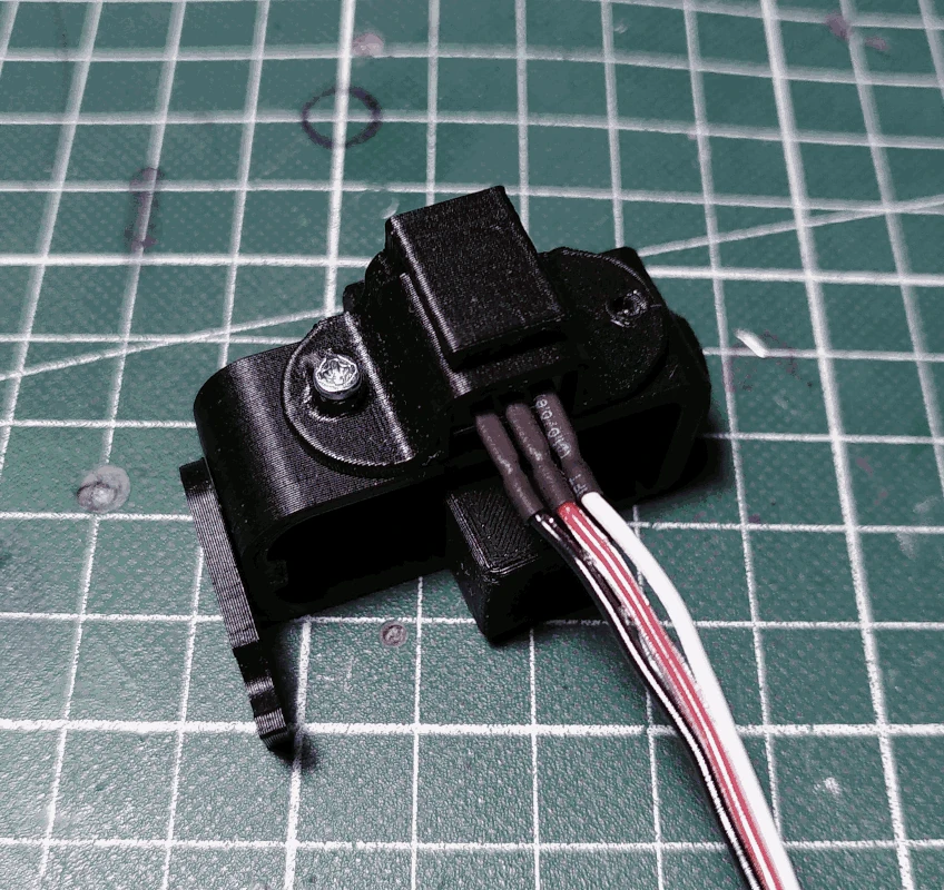
Guide the wires from both the potentiometers through the
cable_clip and leave enough wire both before and after so that the
bridge can spin freely without the
bearing and
cable_holder having to move.
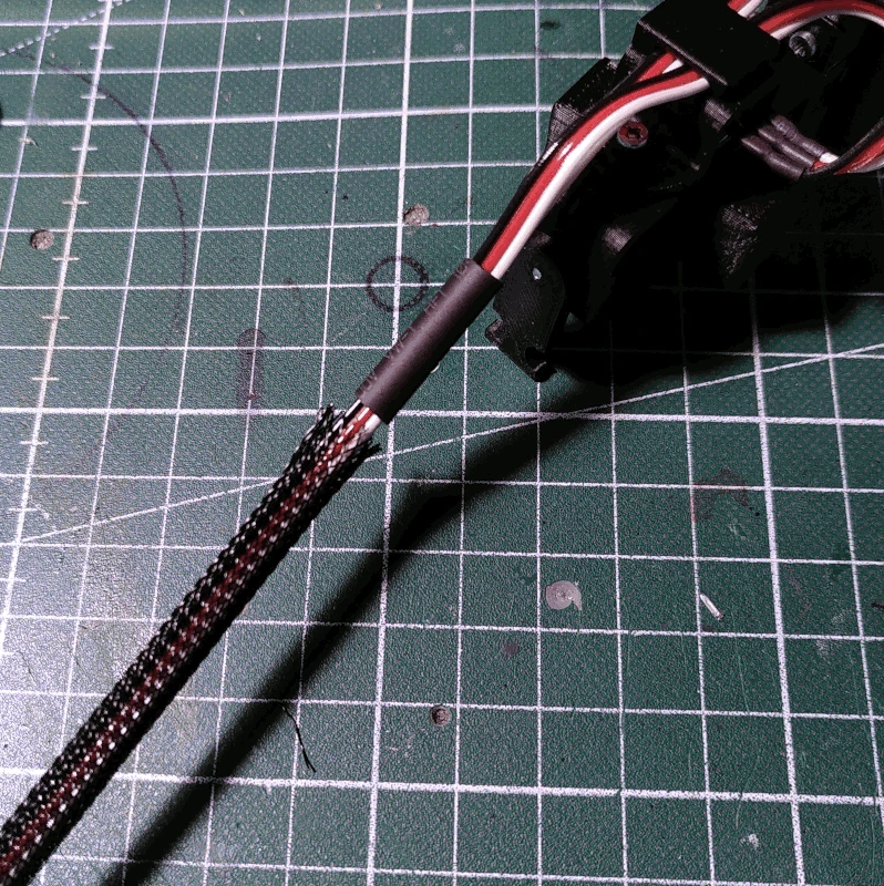
Slide on a ca 2cm length of heat shrink tubing unto the wires. In the image below the white wires will be connected to 5V+. It's recommended to align them this way (having the wires to be connected to 5V+ on this side) since it will ensure the servos turn in the appropriate direction relative to the turning of the potentiometers.
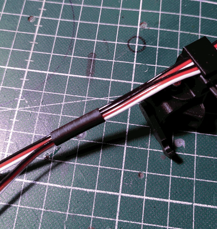
Cut a length of 6mm cable sleeve to about 17cm and slide the wires through it.
Slide on a ca 4cm length of heat shrink tubing wide enough for the cable sleeve to fit into, and cover about half of the smaller heat shrink tubing like depicted below. Before heating make sure there's enough wire before it so that the
bridge can move freely without the
bearing or the
cable_holder having to move.
After heating, attach the cable to the
cable_holder using a small zip tie.
Before attaching connectors, insert the wires into 2 pieces of heat shrink tubing, one smaller and one larger, in the same fashion as before.
Attach female pins and 3x1 Dupont connector housing. If you've kept track of which wires were soldered to which pins and also aligned them as previously demonstrated, it will be easy to connect them to the board later on. If not, there is a possiblity that
some connector will have to be flipped (lest some movements be reversed in relation to which direction the potentiometers are turned).
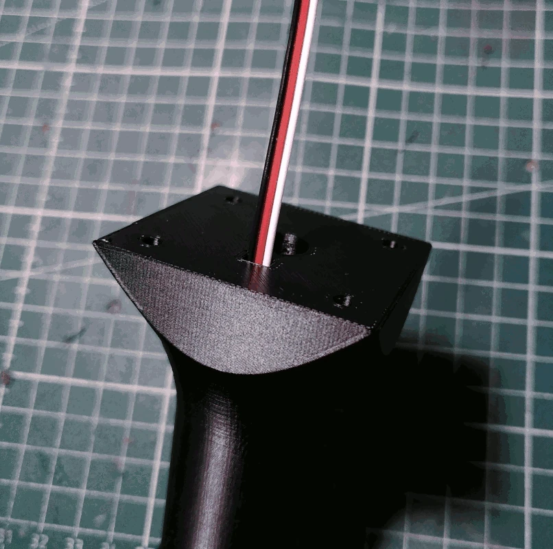
Cut 3x1 wires to a length of about 20cm and guide it through the small square hole in the bottom of the part labelled
handle.
Grab the other 10Kohm potentiometer with a metal shaft and, like before, strip it of everything besides the necessary 3 pins but keep the legs bent downward.
While making sure the wires stay in the
handle, solder them to the pins of the potentiometer. For this potentiometer it's not really important to keep track of which wire is soldered where as long as you remember which wire is soldered to the middle pin (the signal pin). It's trivial to change places for GND and 5V+ for this potentiometer should the movement be reversed in relation to in which direction the potentiometer is turned.
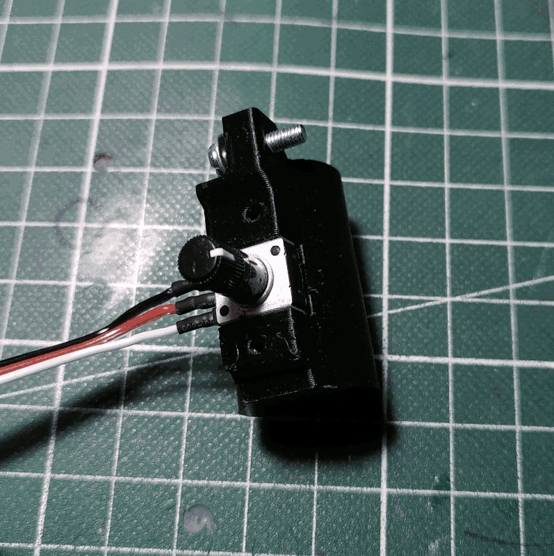
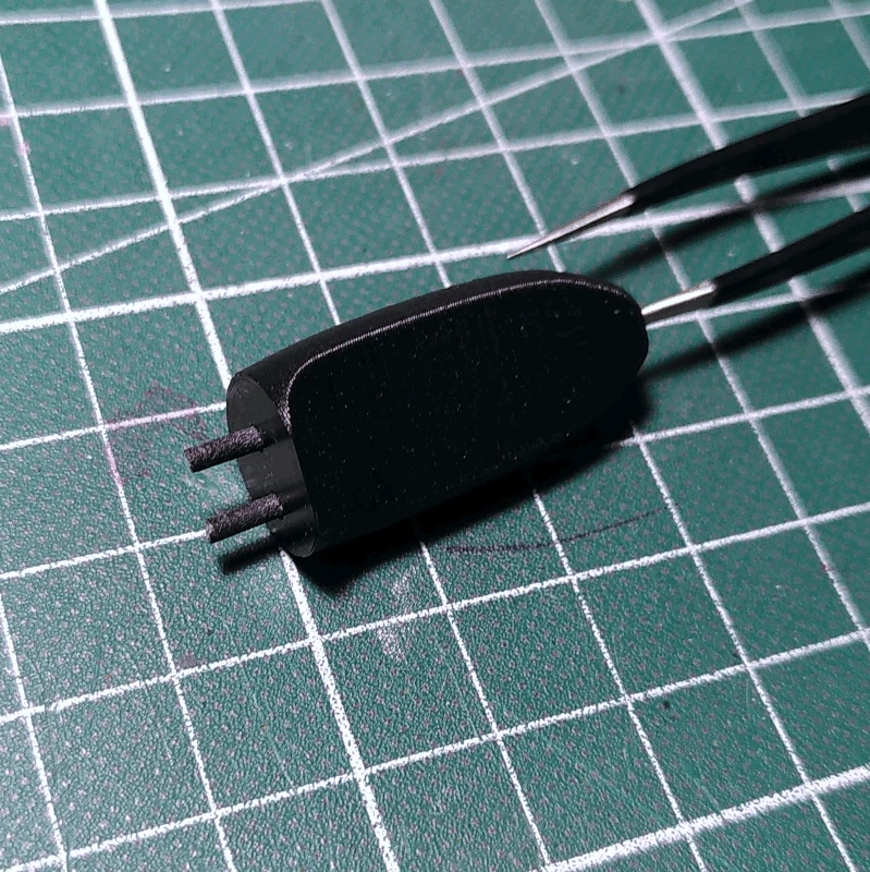
Mount the potentiometer in the
handle like depicted below and fasten the part labelled
handle_pot_holder to the
handle using 2 M3x12mm screws.
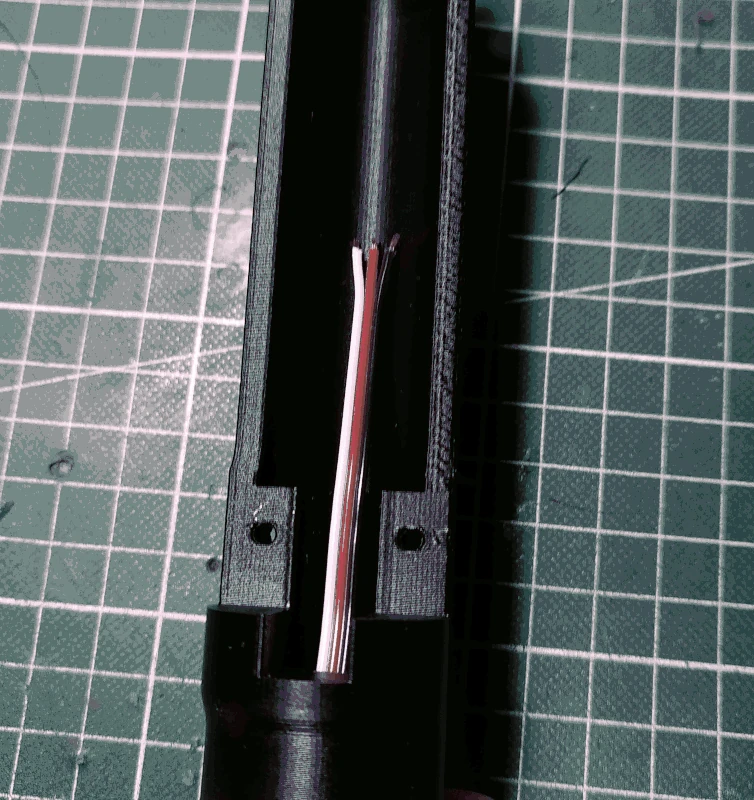
Make sure nothing protrudes within the shaft. If the potentiometer legs are visible you'll have to bend them in a bit.
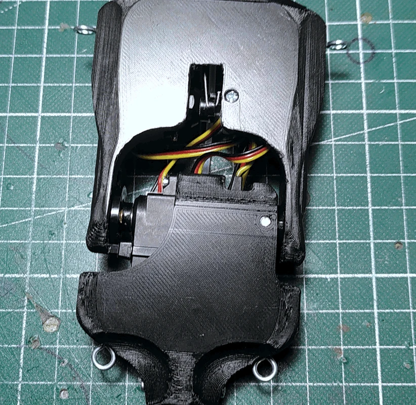
Grab the part labelled
housing and insert M3 nuts into each corner (there are slots for them). Next grab the
handle, guide the wires from the potentiometer through the square hole on the top side of the
housing.
Next, fasten the
handle to the
housing using 4 M3x12mm screws (due to the square holes there's only one possible orientation).
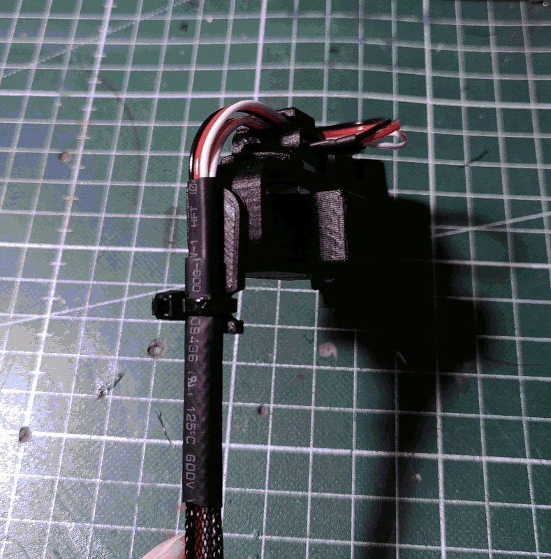
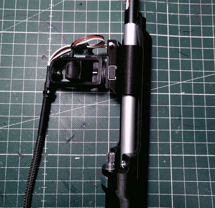
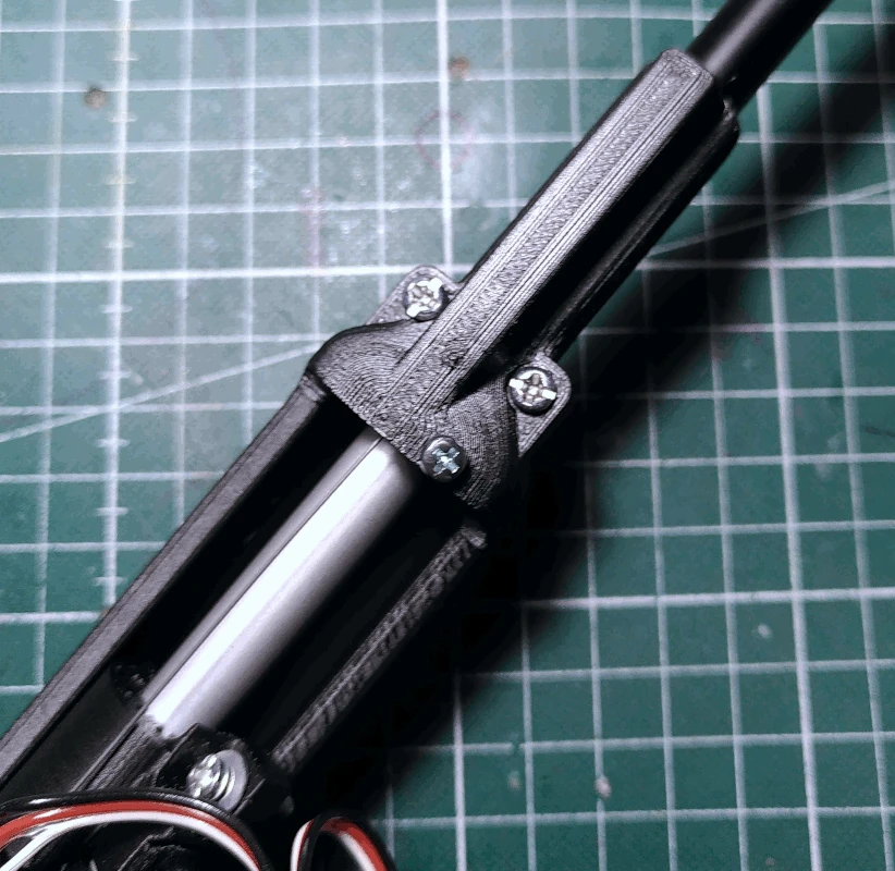
Slide the rod through the
bearing (from the end of the rod which is not painted).
Insert the rod in the
handle. The front of the rod should be facing in the same direction as the side of the handle on which the potentiometer is mounted, as depicted below.
Secure the rod to the
handle using a M2x19mm screw.
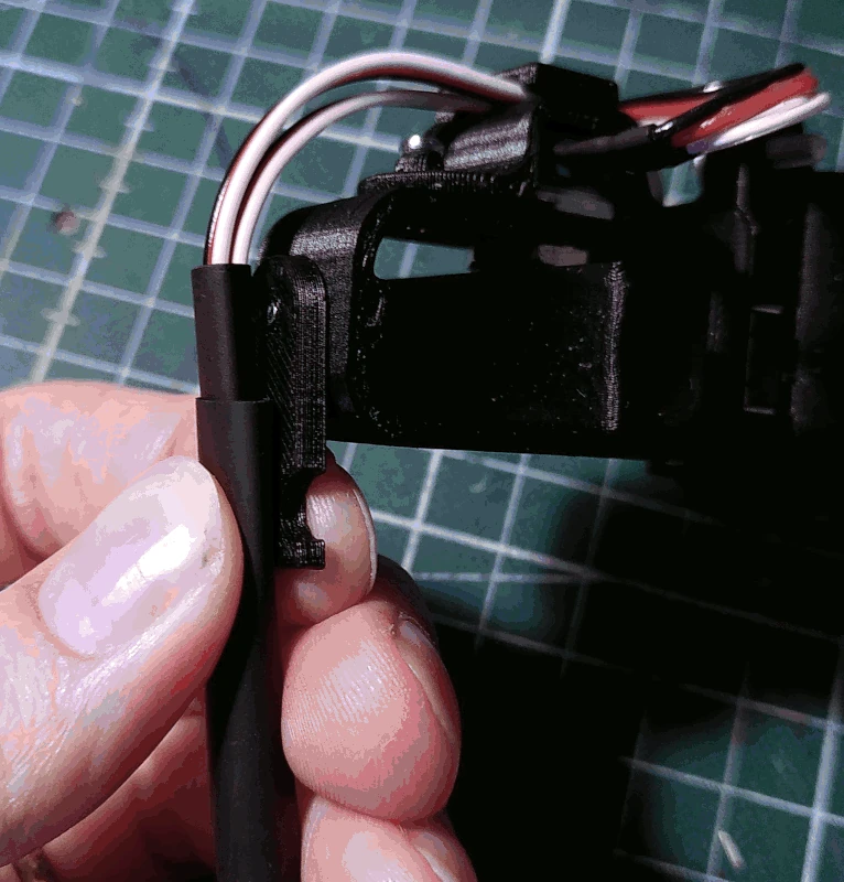
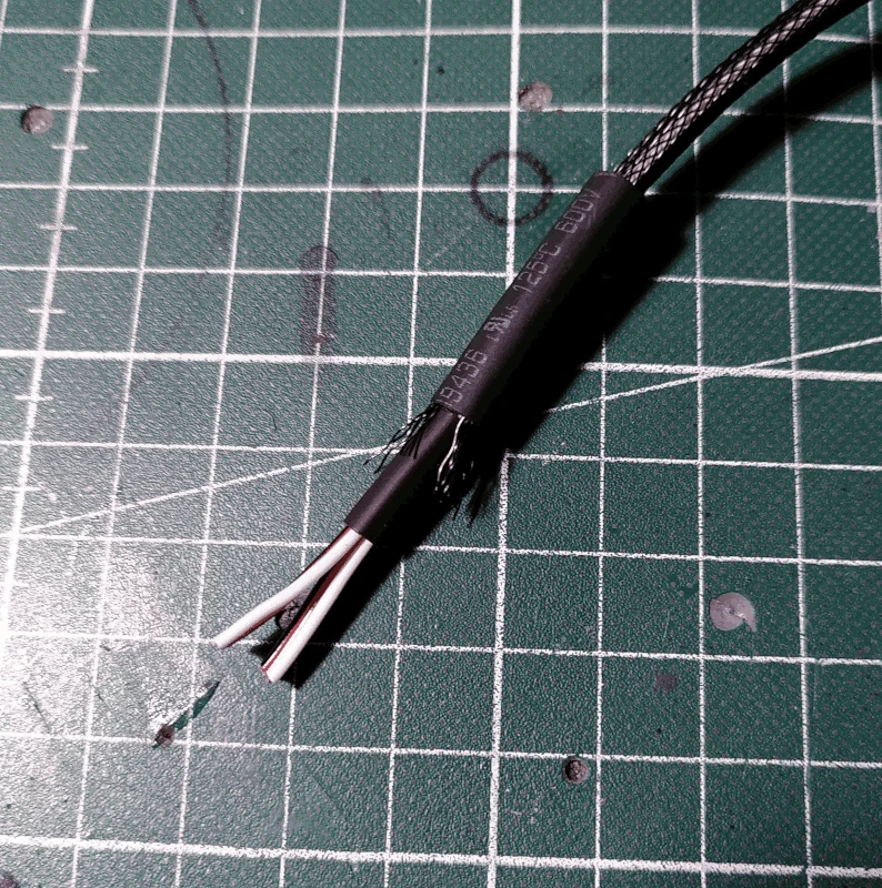
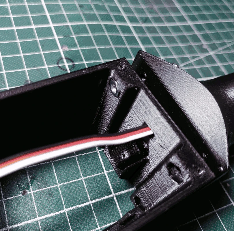
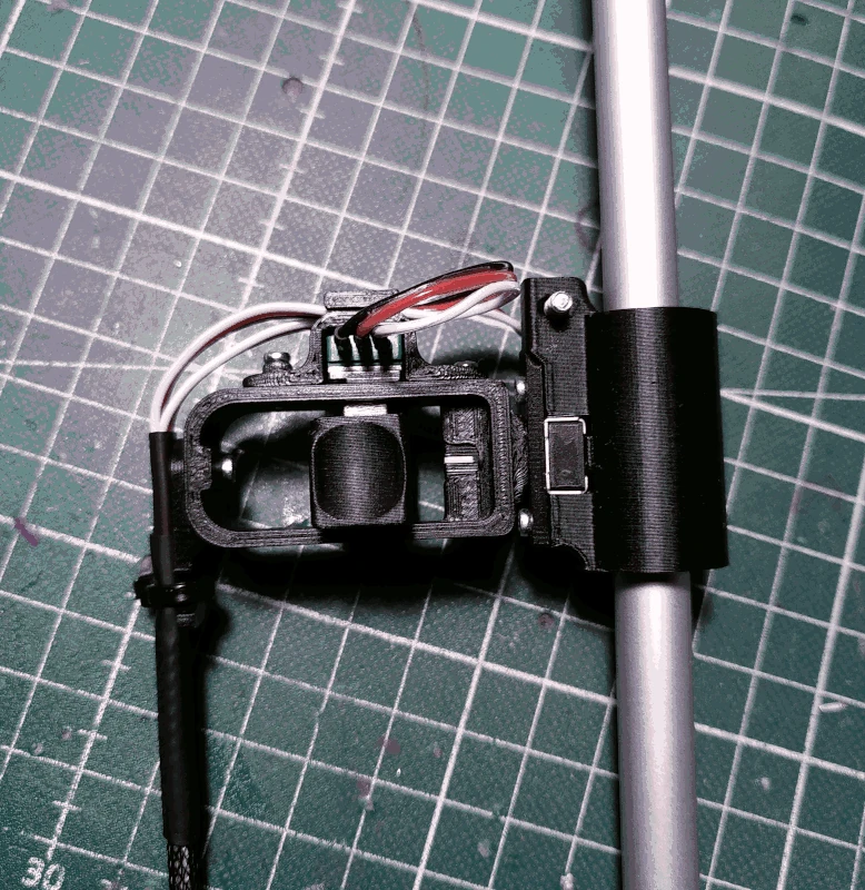
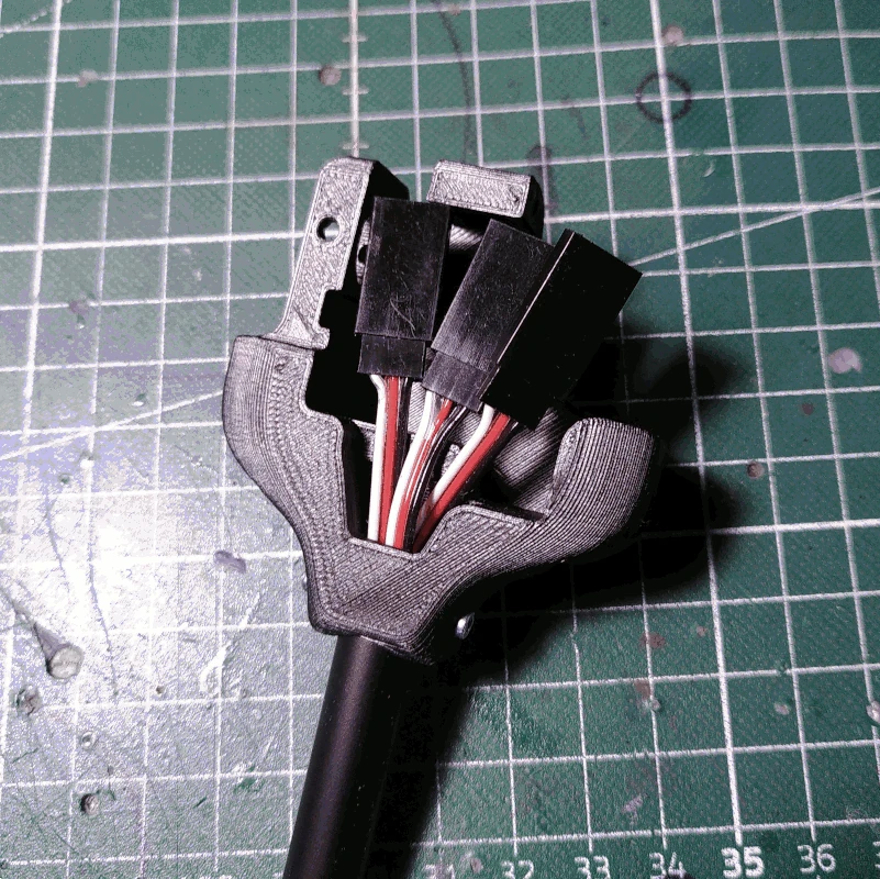
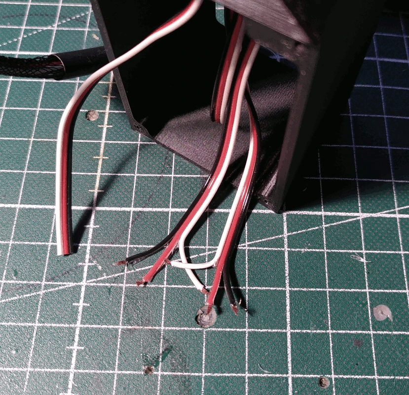
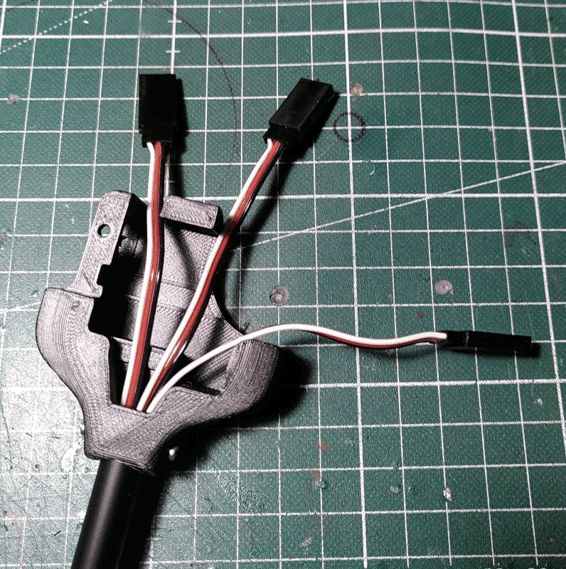
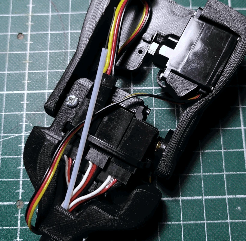
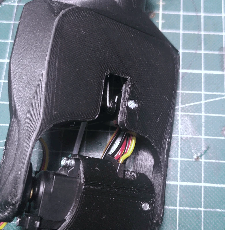
The wires coming from the bottom end of the rod can be shortened. If the wires coming from the top of the rod (the ones that you attached connectors to previously) protrude as much as
can be observed in the left picture below, the wires coming from the bottom end of the rod can be cut so that they protrude around 6cm from the bottom end of the rod.
The wires attached to the potentiometer
attached to the
controller_handle can be cut to match the length of the other wires.
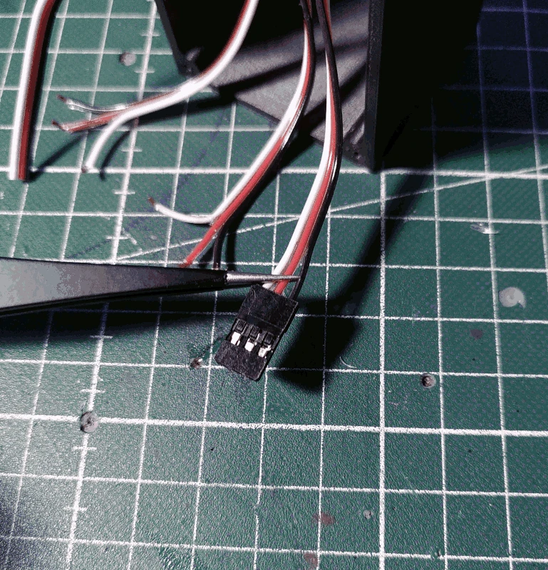
After shortening, attach female pins and 3x1 Dupont connector housing to the wires coming from the rod.
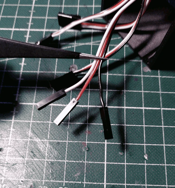
Attach female pins and 1x1 Dupont connector housing on each individual wire of the wires from the potentiometer attached to the
handle.
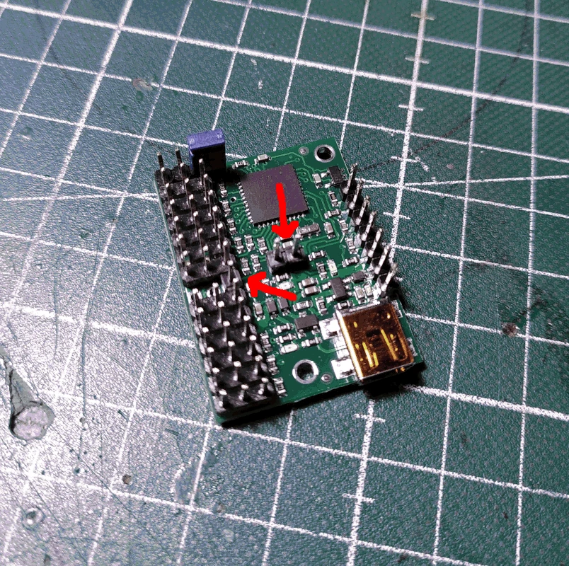
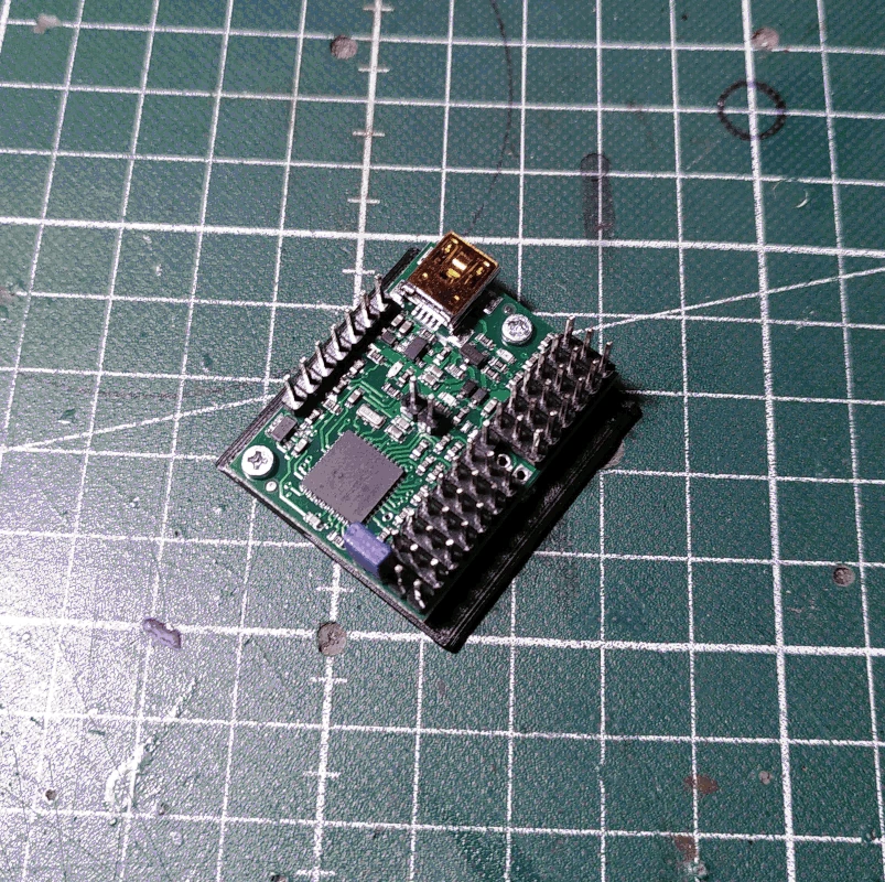
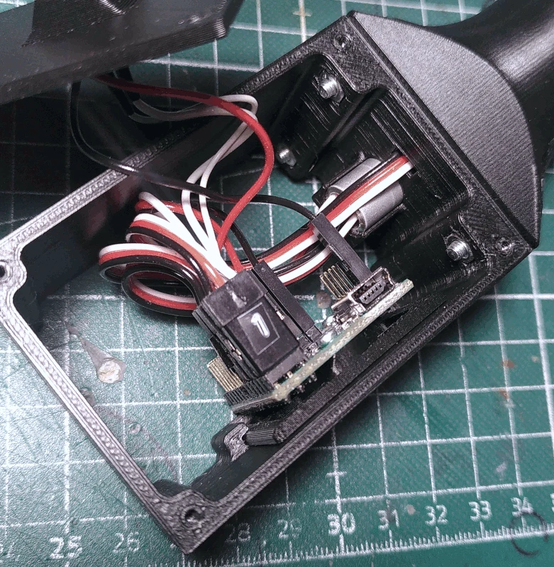
Grab the Mini Maestro controller board and solder header pins to the 5V OUT situated in the middle of the servo connector rail as well as to the 5V OUT and GND situated in the middle of the board.
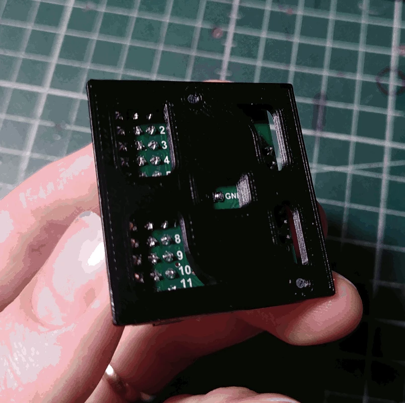
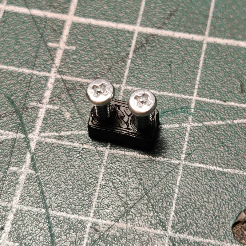
Attach the controller board to the part labelled
board_holder using 2 M2x6mm screws.
The markings on the bottom of the board are still visible.
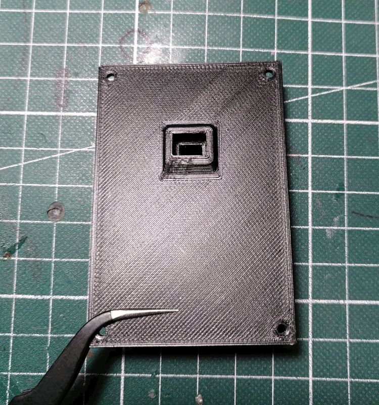
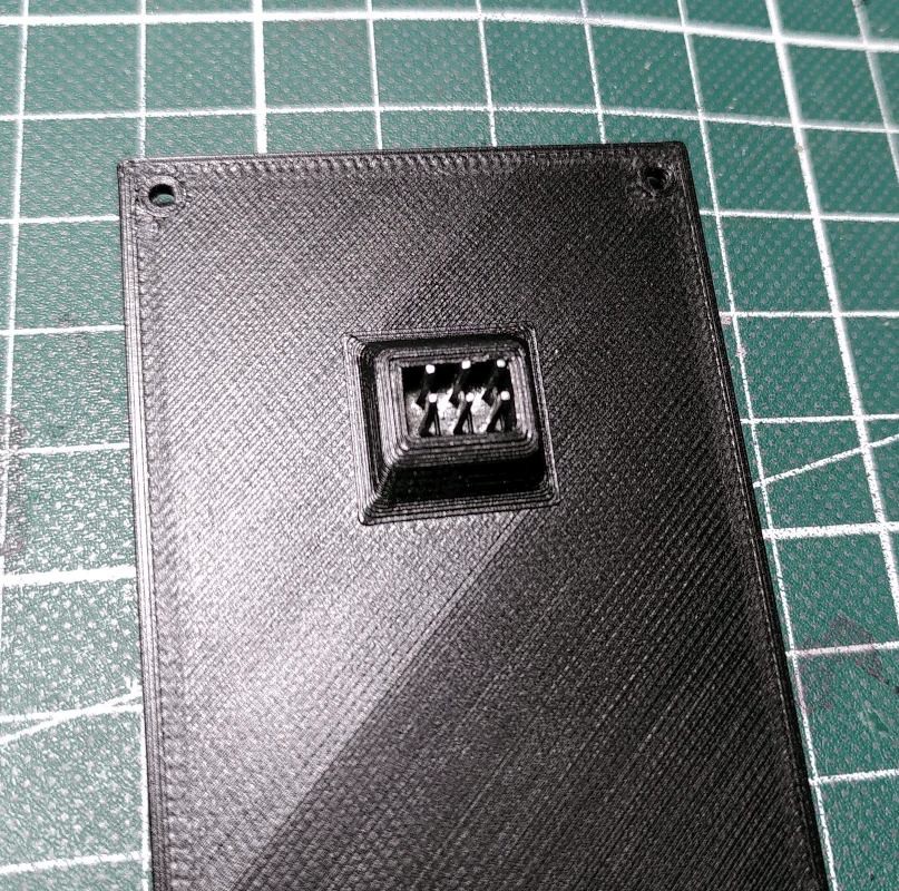
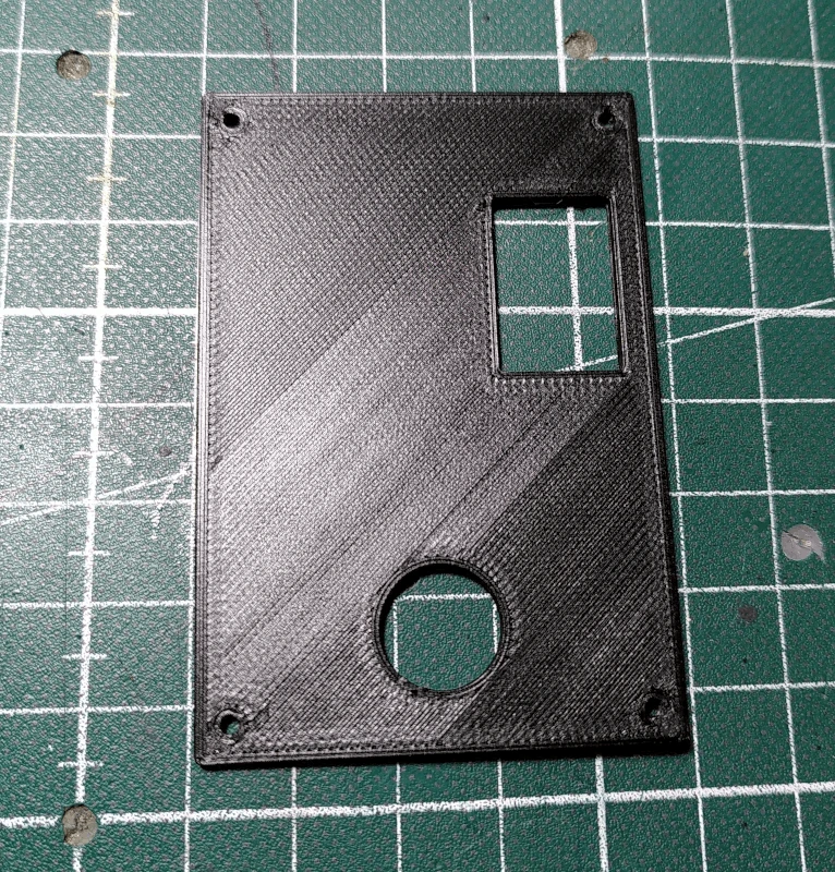
Grab the part labelled
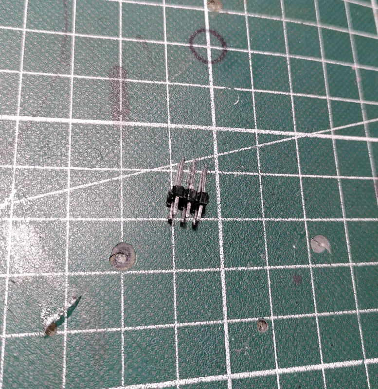
front_lid and prepare 3x2 header pins.
Glue the header pins in the mounting hole on the
front_lid and make sure they protrude evenly in the back.
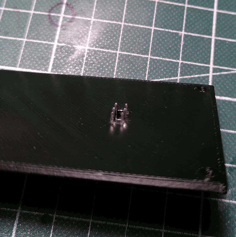
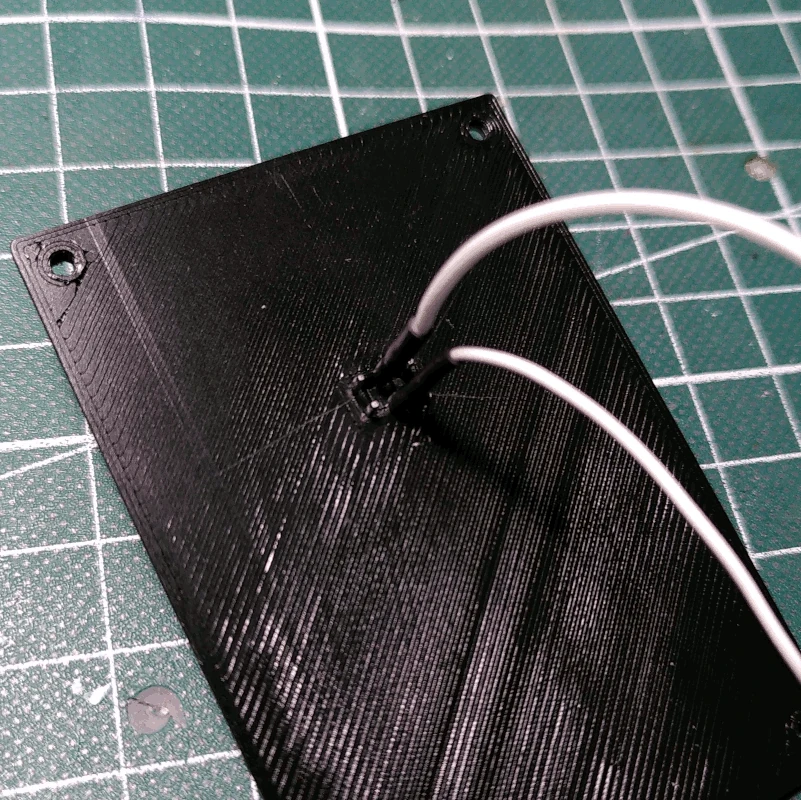
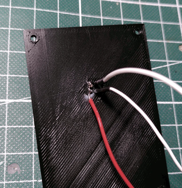
Solder wires to the middle pins, solder them at an angle as depicted below. These will be signal lines.
Solder a wire to both of the outer pins, on both sides. With the back side towards you, the left most pins will carry 5V+ and the right will be GND.
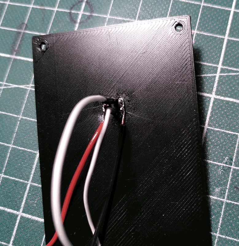
After having soldered the wires grab the part labeled
lid_pin_stop, guide the signal lines through the holes and fasten it to the
front_lid using 2 M2.5x4mm screws.
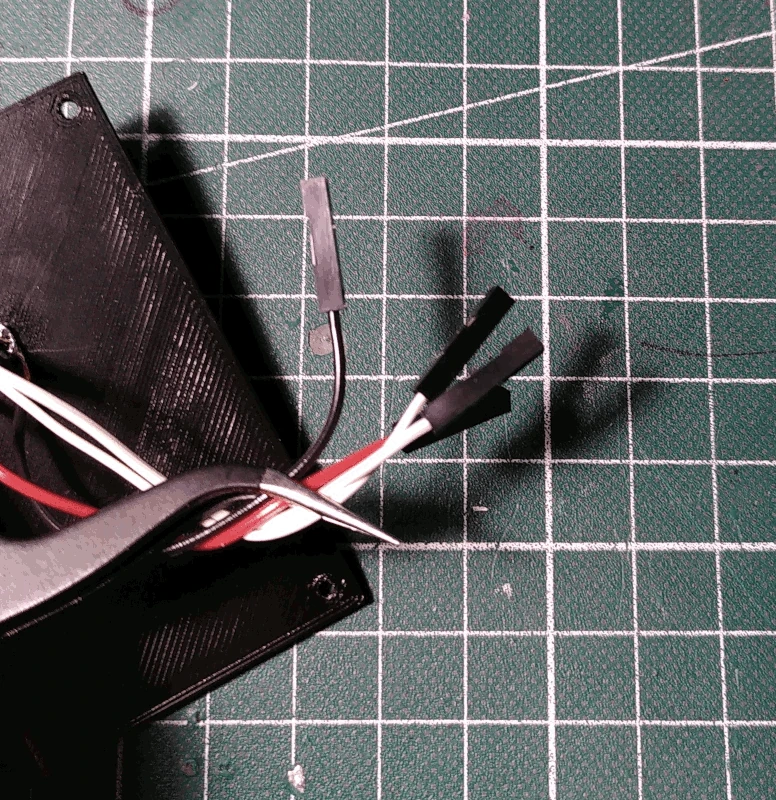
Cut them to a length of ca 7cm and attach female pins and 1x1 Dupont connector housing.
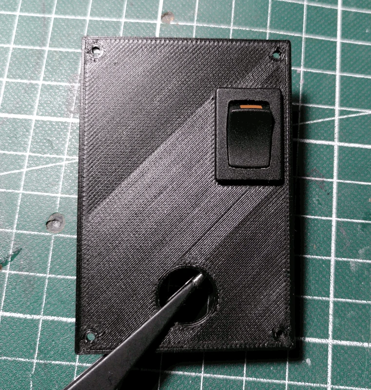
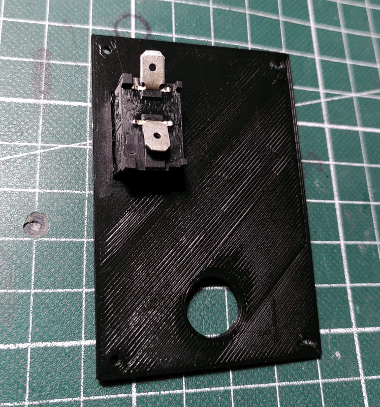
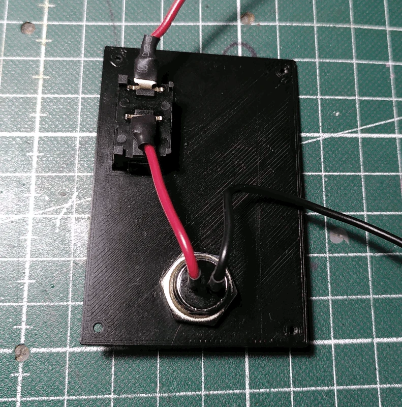
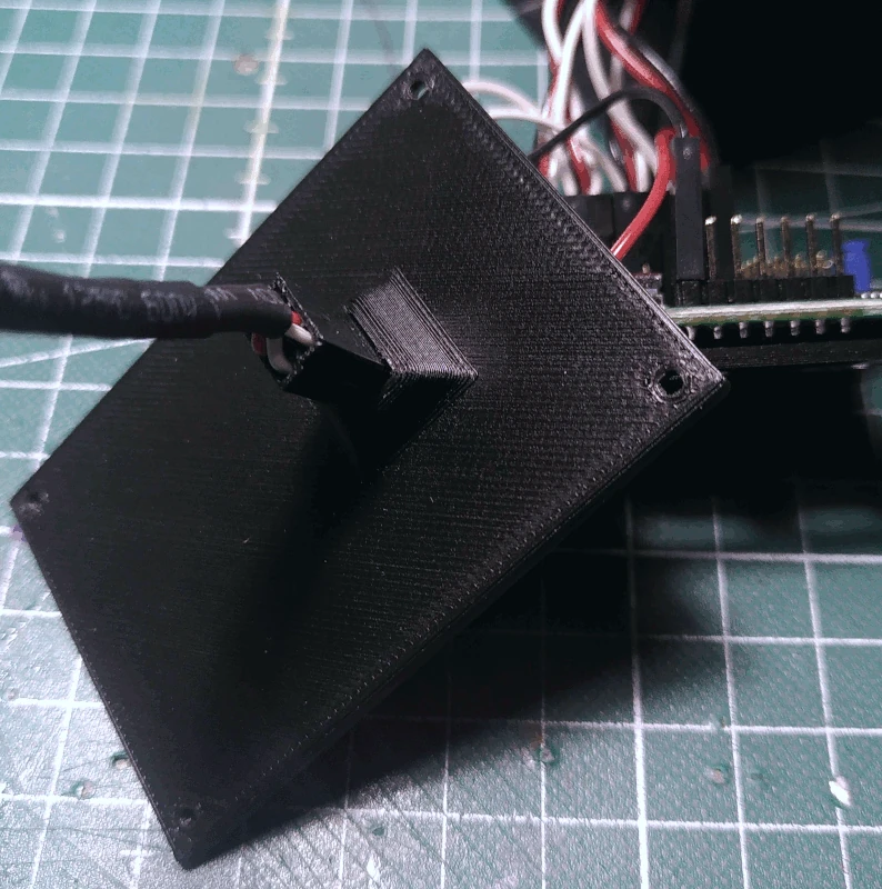
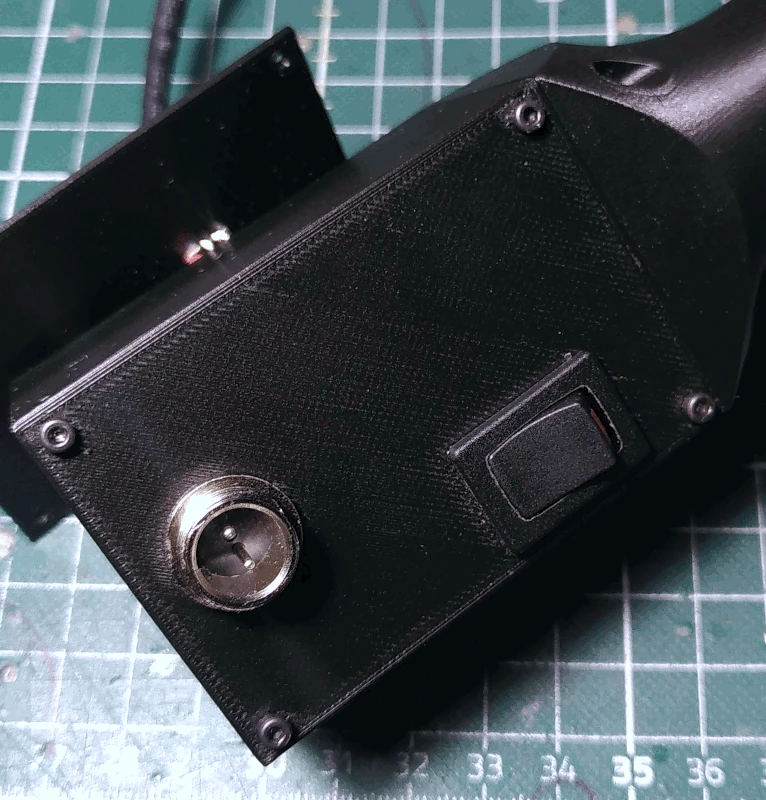
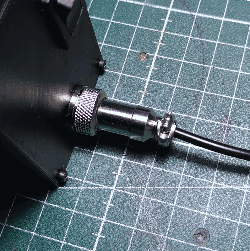
Grab the part labelled
back_lid and insert the ON/OFF switch on the front side (mounting hole to the right).
It's recommended to bend the pins somewhat.
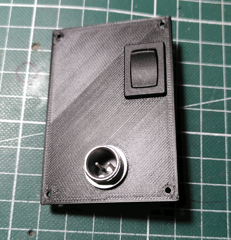
Mount the GX12 jack into the round mounting hole.
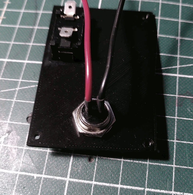
Solder wires to the pins of the GX12 jack, use something a bit thicker than servo wires and cover the connections with heat shrink tubing. The left pin is best used for the 5V+ (red wire in the image below).
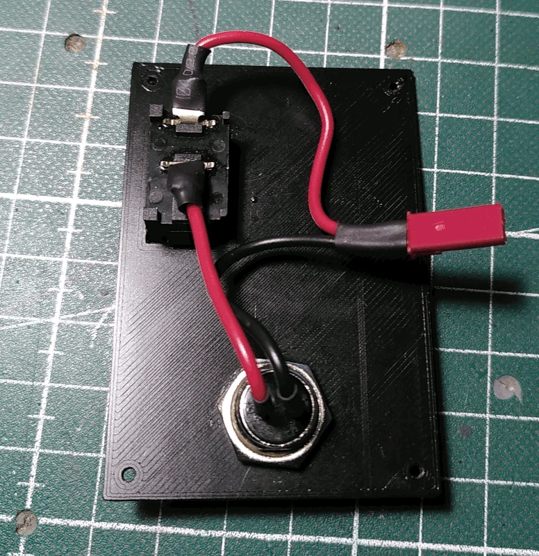
Connect the wire on the left pin to the switch and solder another wire to the other pin of the switch.
Shorten the wires a bit (see below image for reference) and attach female pins and the BEC connector housing to the ends. It's a good idea to keep them together with a bit of heat shrink tubing.
Attach the part labelled
torso_control_knob to the potentiometer mounted on the
handle.
Grab the part labelled
torso (if you've printed this with a brim as recommended, it's of course a good idea to do some cleanup before proceeding although it doesn't really have to look perfect) and insert the servo screw for the D89MW servo in the lower mounting hole on the side where there are two holes.
Mount a circular servo arm for the D89MW servo on the inner side of the
torso, using the servo screw to keep it centered. Since the servo arms might differ in size there are no holes in the model for the screws, so use sharp screws such as those made for wood working.
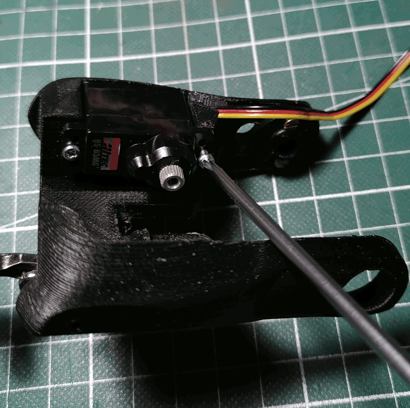
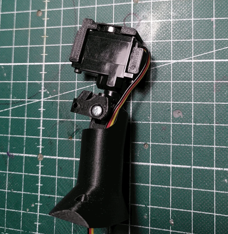
Mount one of the HS65MG/BB servos in the
torso using 2 M2x6mm screws.
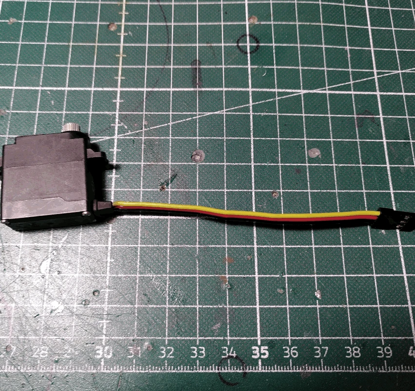
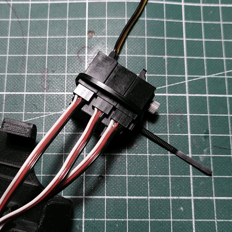
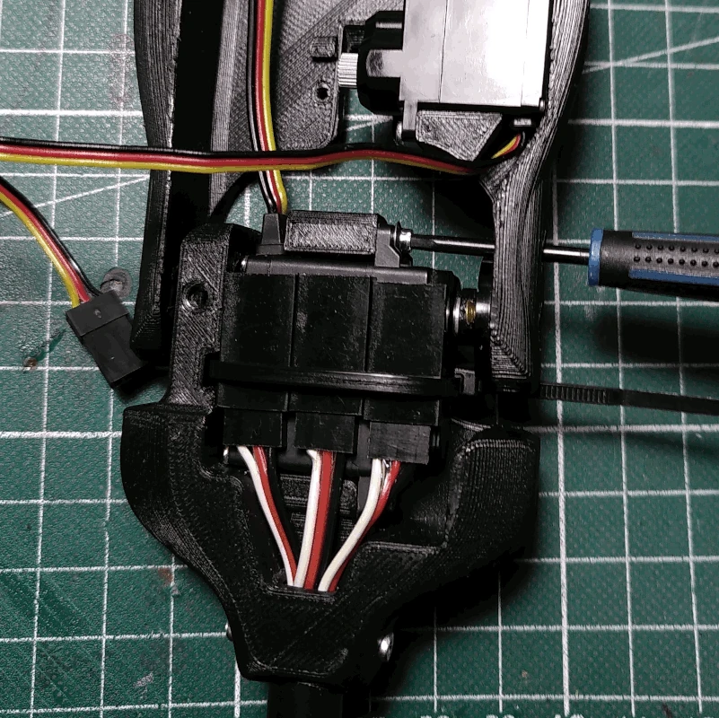
Grab the D89MW servo and shorten the cable to around 9cm.
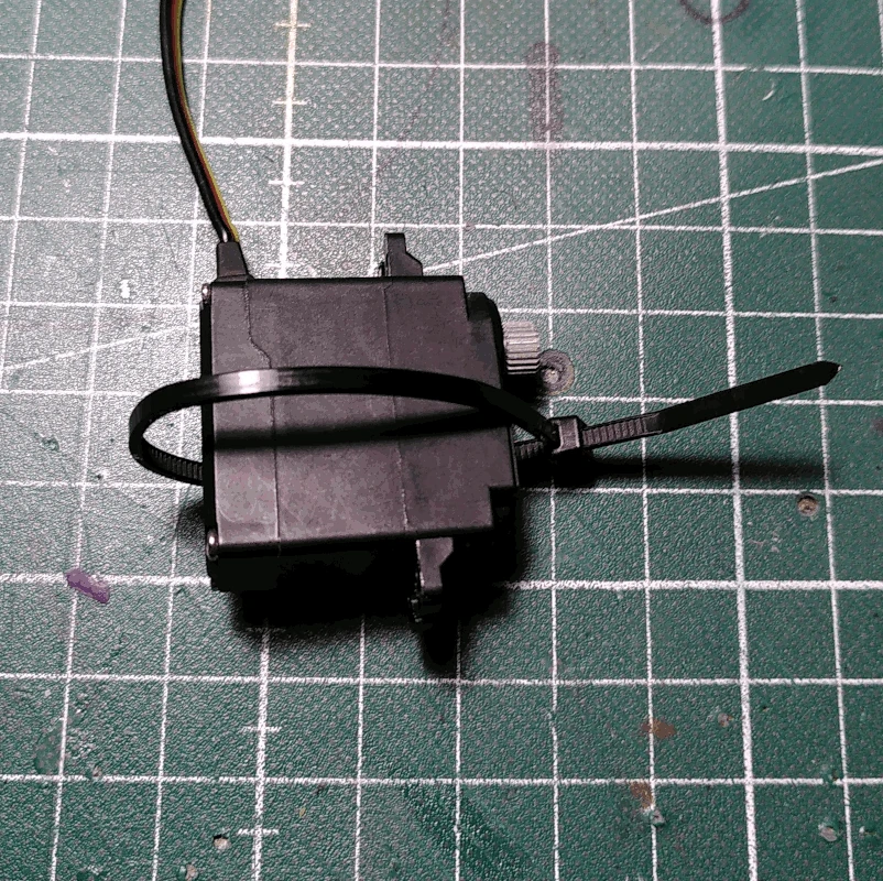
Next, grab a 2.5mm ziptie and tie it around the servo body but don't tighten it yet.
Pull out the wiring from the rod as much as possible.
Fasten the connectors to the D89MW servo body using the zip tie.
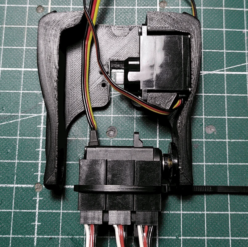
Set the D89MW servo to it's middle position and attach it to the circular servo arm attached to the
torso.
Mount the D89MW servo to the
hip, pull back the wires from the rod from the bottom and secure the servo to the
hip using servo screws. There are holes on the sides of the
torso and
hip to allow for this.
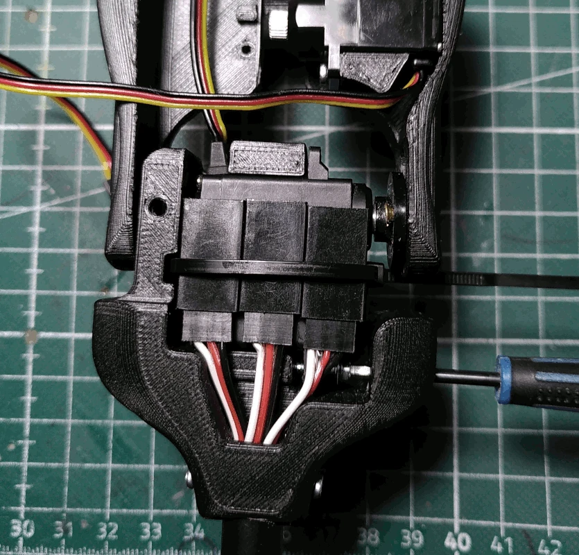
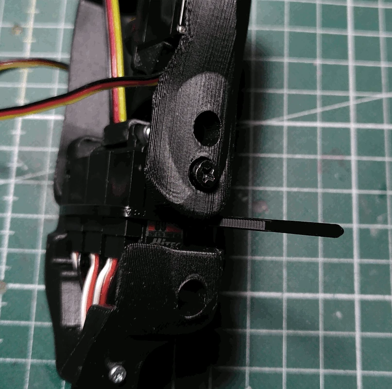
Secure the torso to the servo with the servo screw and trim off any excess from the zip tie.
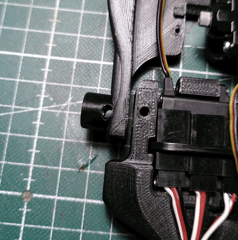
Grab the part labelled
torso_shaft and insert it on the side of the
torso opposite from where the servo is mounted.
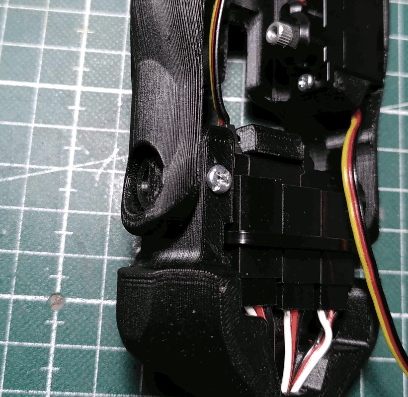
Insert it all the way into the
hip, align it and secure it to the
hip using a M3x19mm screw.
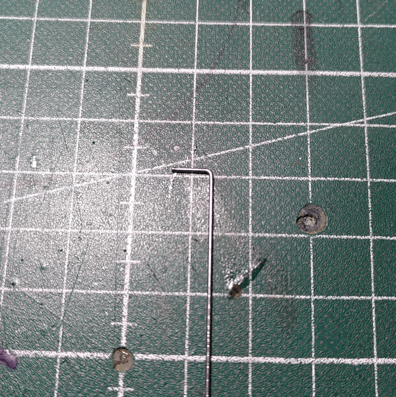
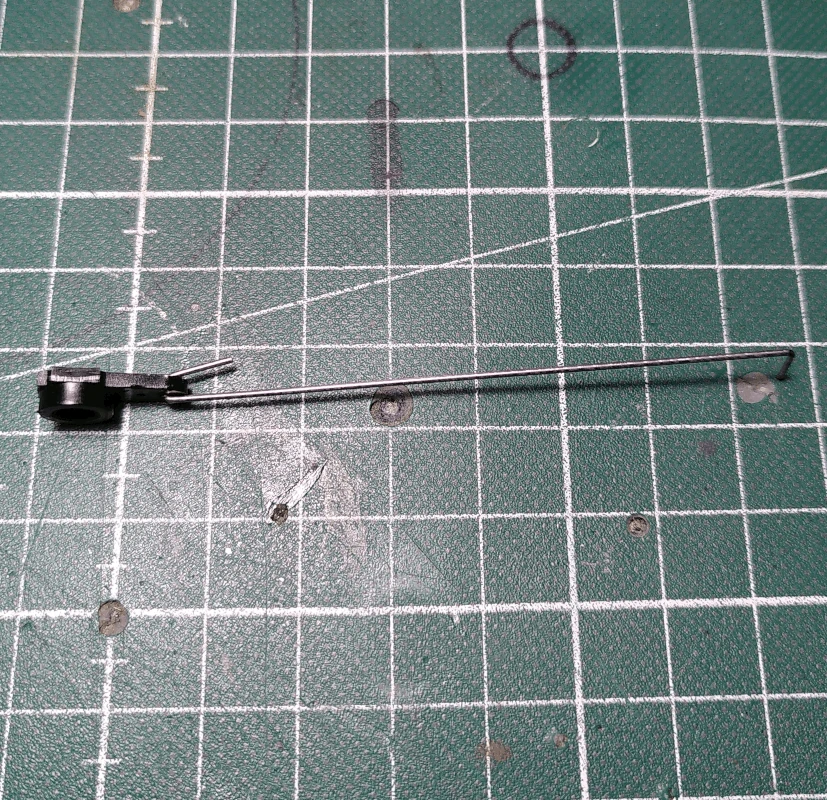
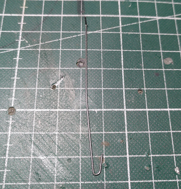
Cut a 9cm length of 0.8mm piano wire and make a mark 7mm in from one of the ends and another mark 10mm in from the other end.
At the 7mm mark, bend the wire 90 degrees.
At the 10mm mark, bend it 90 degrees but rotated 90 degrees in relation to the other end (see below right image).
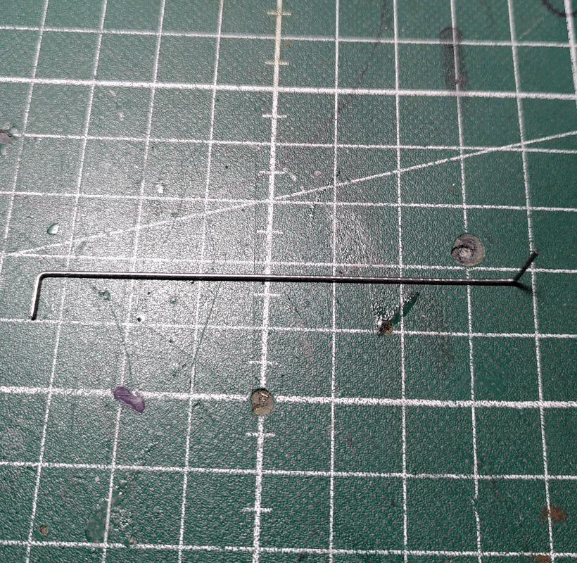
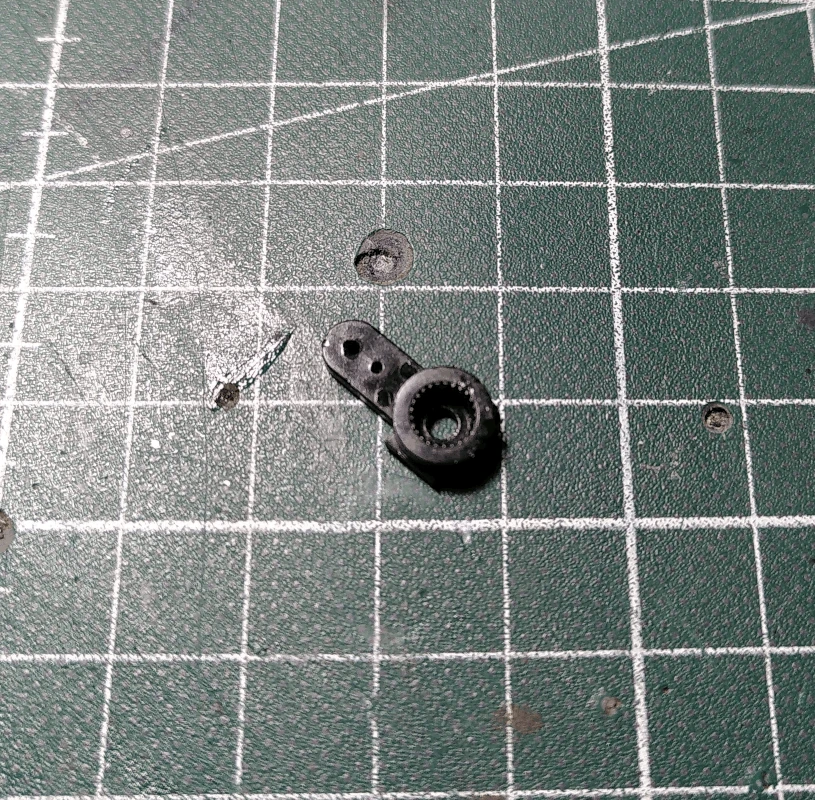
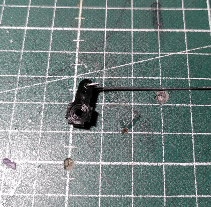
Grab a 4 way servo arm for a HS65MG/BB servo and cut away all but one of the arms (it can be any servo arm as long as it's not longer than about 12mm, measuring from the center of the servo shaft).
Insert the end of the piano wire which was bent at the 10mm mark in the outer hole of the arm and bend it so that it hooks the arm (as shown below). The wire should be able to rotate freely but should wiggle as little as possible from side to side .
Bend the wire slightly in the middle so that it looks something like what's shown in the below image.
Trim of the excess from the end of the wire that's hooked into the servo arm.
Grab another 4 way servo arm for a HS65MG/BB servo and remove one of the arms. Glue it unto the part labelled
head_base using a strong glue.
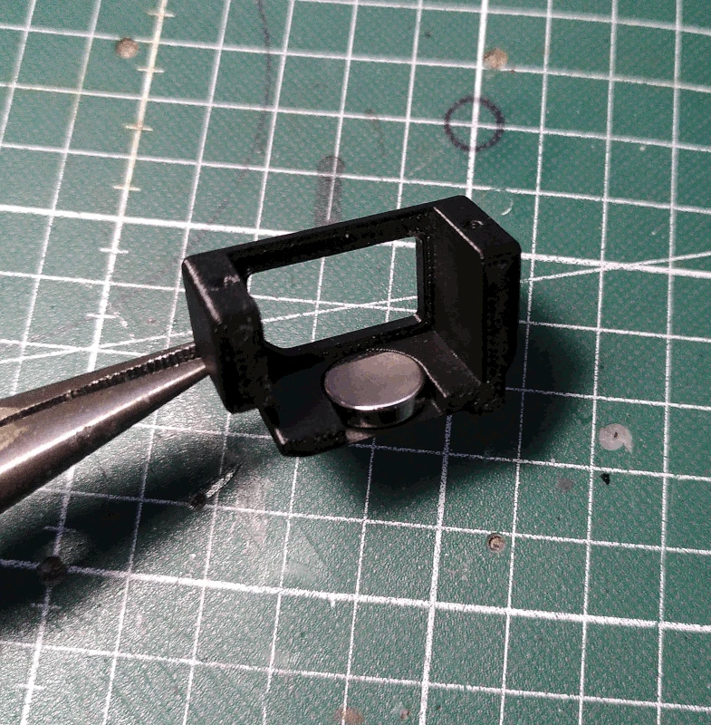
Grab the part labelled
headservo_holder and attach a 12x3mm neodymium magnet using a strong glue.
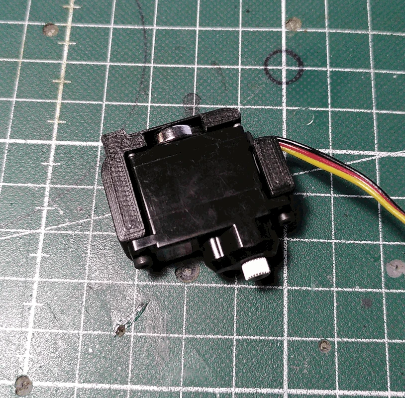
Mount a HS65MG/BB servo in the
headservo_holder using 2 M2x6mm screws.
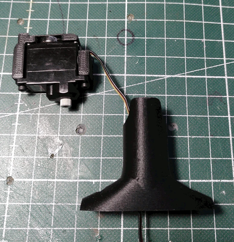
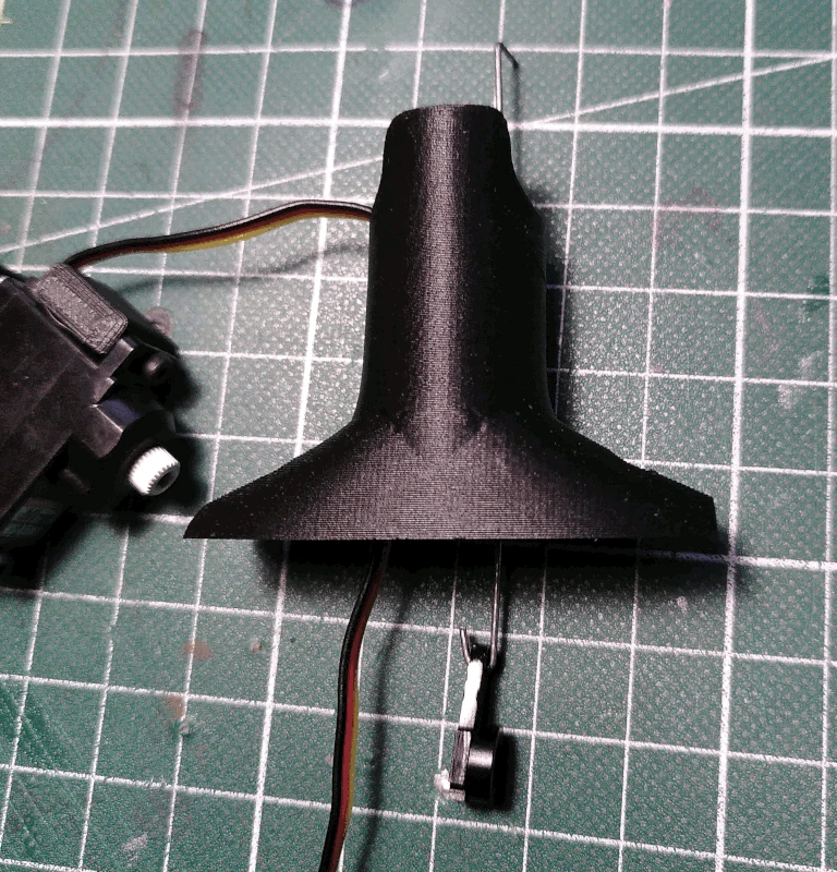
Grab the part labelled
neck and, while keeping it front face down as shown in the image below, insert the cable from the servo mounted in the
headservo_holder into the left hole.
Insert the piano wire previously prepared (keeping the servo arm hooked and placed as shown in the image below) into the right hole.
Insert the top end of the piano wire into the smaller hole of the part labelled
neck_bridge.
Flip the whole thing over and fasten the
neck_bridge to the
neck using a M2x12mm screw. It should be loose enough so that the
bridge can rotate freely.
Attach the
head_base to the
neck_bridge using 2 M2.5x4mm screws on both sides. The screws fasten in the
head_base itself and should be able to rotate freely in the sockets on the
neck_bridge.
Set the servo mounted in the
headservo_holder to it's middle position and mount it on the servo arm attached to the
head_base, oriented so that the longer side of the servo is perpendicular to the front side of the
head_base (see below image).
Grab the part labelled
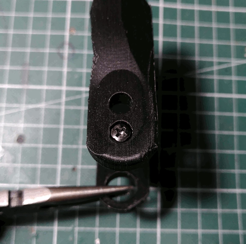
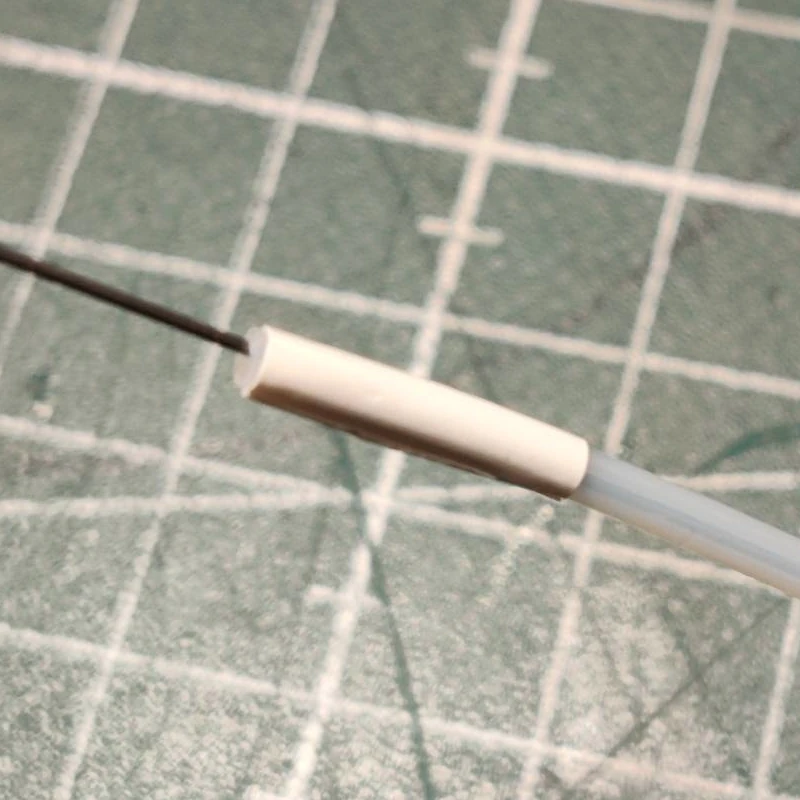
handle_tube_holder and attach a M2.5x4mm into the mount hole in the front as depicted below. It does not have to tightened.
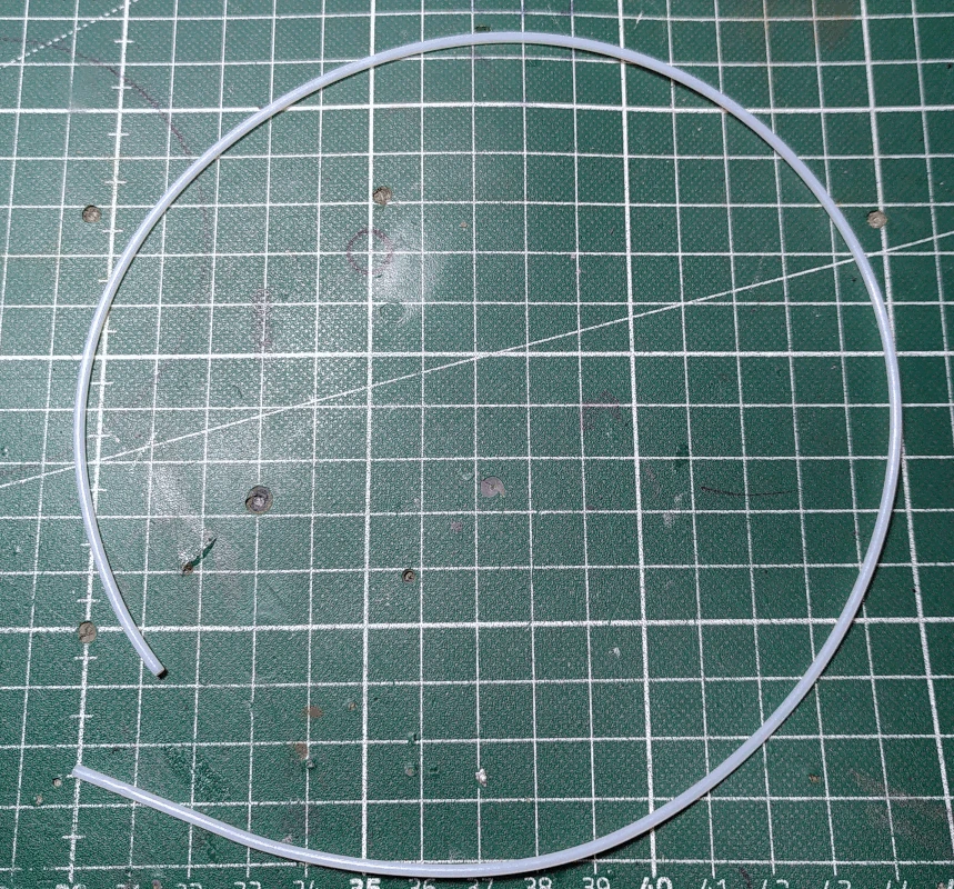
Cut the 0.5mm piano wire to a length of ca 58cm and also cut a 48.5cm length of 2mm PTFE tubing. The length of the PTFE tube affects by how many degrees the upper body can bend forward before the tube is pulled out of the
neck and how much of the tube will protrude from the back when up right or bent backwards. The length given here is chosen simply because I think it offers a good balance. To view how much the body can bend forward with this length, watch the demonstration video. Note that if you should increase the length of the PTFE tubing considerably you may also have to increase the length of 0.5mm piano wire (there should be around 5cm of wire protruding from both ends of the tube).
Insert the piano wire into the PTFE tubing. If you feel resistance while doing so you can spray the wire with silicone/PTFE lube spray as you go along. Leave a length of ca 5cm protruding from each end.
Grab the part labelled
handle_tube_holder_2, place it with the ridge for the tube facing downward and fasten 2 M2x6mm screws in each of the holes.
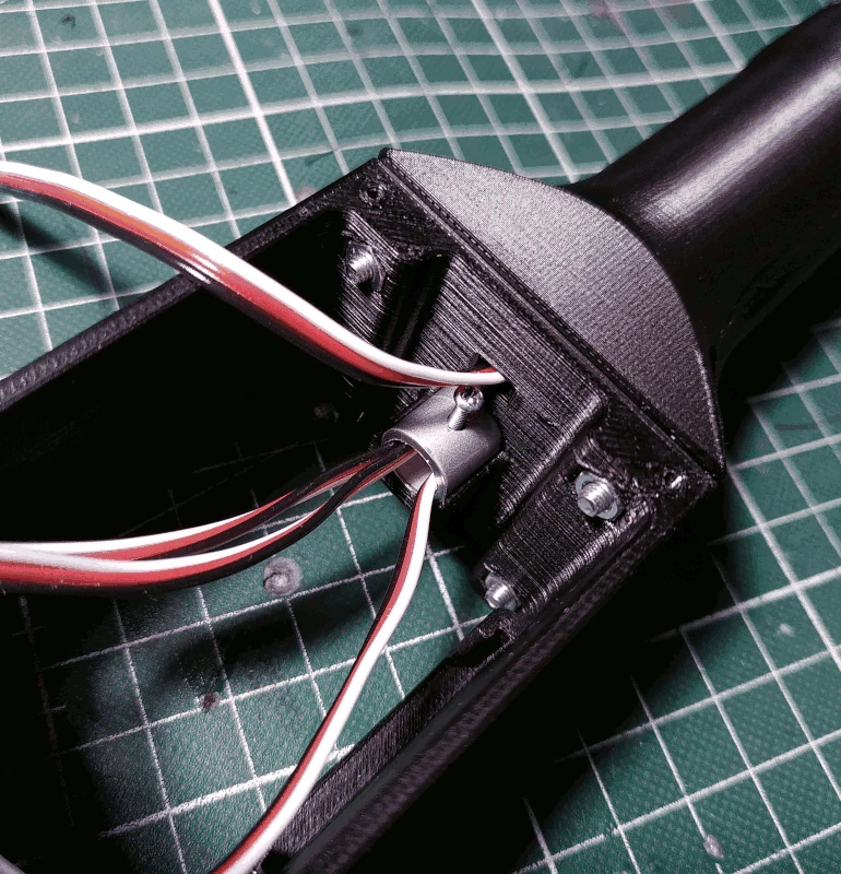
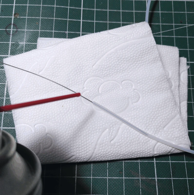
Wrap one of the ends of the PTFE tube with electrical tape (width doesn't really matter). You only need to wrap it one turn, cut of any excess.
After having done so, insert the piano wire protruding from the end wrapped in electrical tape (still inserted into the PTFE tube) into the small hole in the
handle_tube_holder and place the end of the tube in the ridge located just above the hole. Note the placement in the image below, the end of the ridge is raised slightly and as such the tube shouldn't be placed "all the way in".
With the tube held in place by holding the piano wire with one hand, secure the
handle_tube_holder_2 to the
handle_tube_holder. Note the small raise at the end of the ridge on one of the sides of the
handle_tube_holder_2, this end is supposed to match up with the small raise on the
handle_tube_holder, together they act as a stop for the tube.
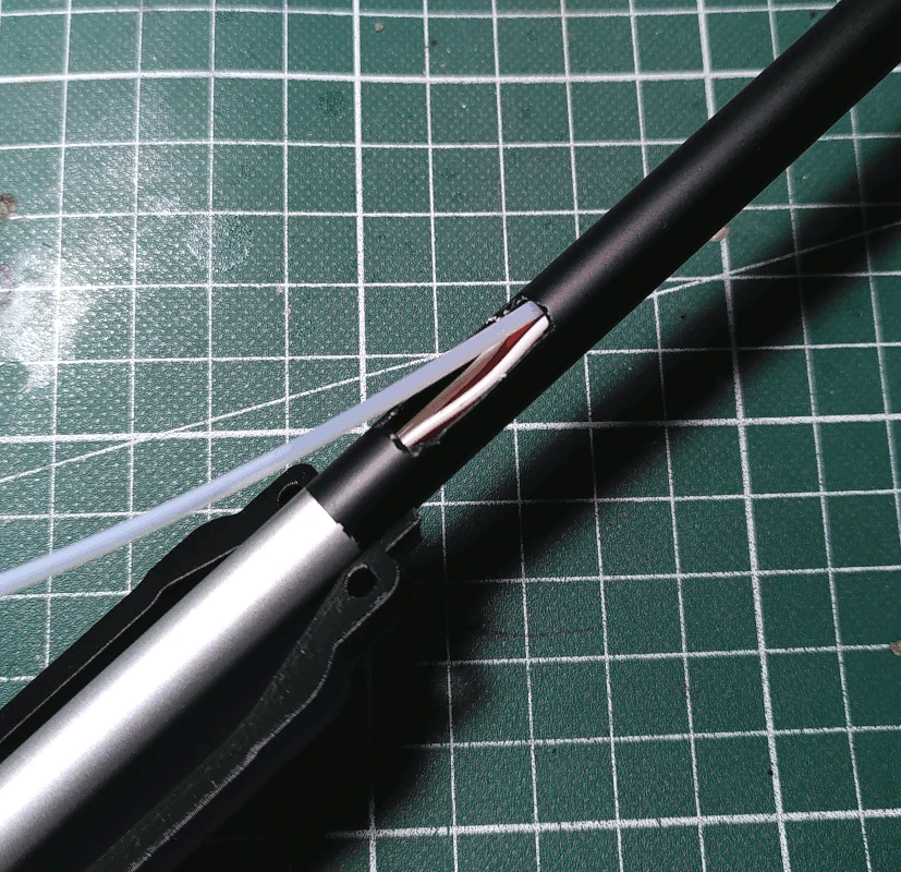
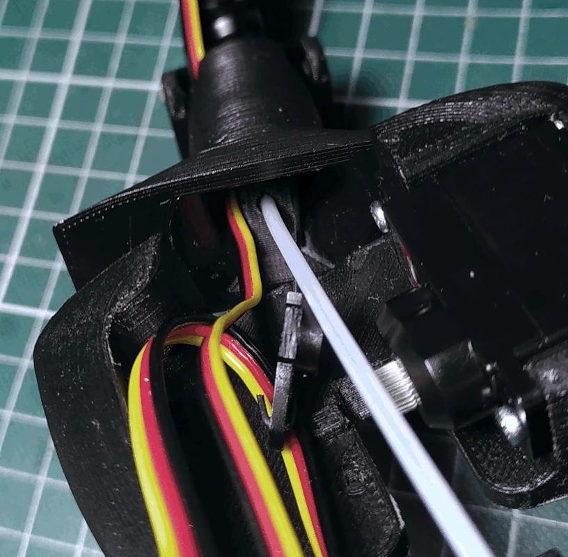
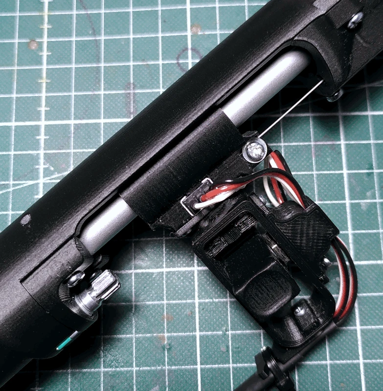
Insert the end of the tube not attached to the
handle_tube_holder into the square hole on the front of the rod.
Slide it all the way through so that it comes out on the other side at the
hip. You may have to jiggle it a bit to get it on the right side of the wiring.
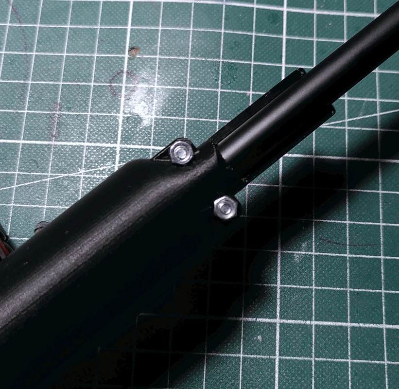
Fasten the
handle_tube_holder to the
handle using 2 M3x12mm screws.
Secure it using M3 nuts on the back side.
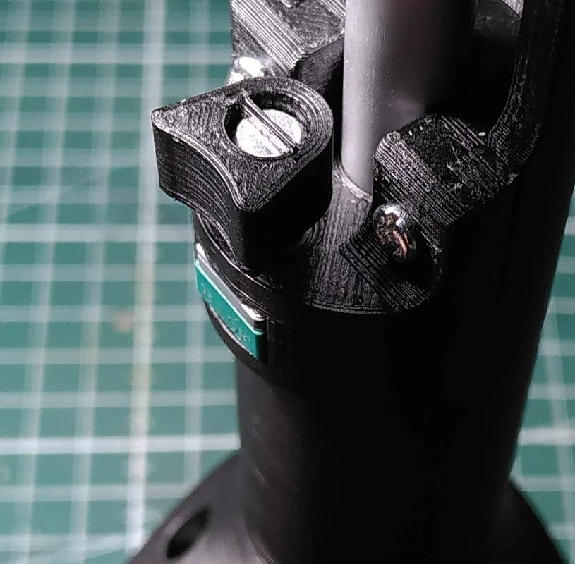
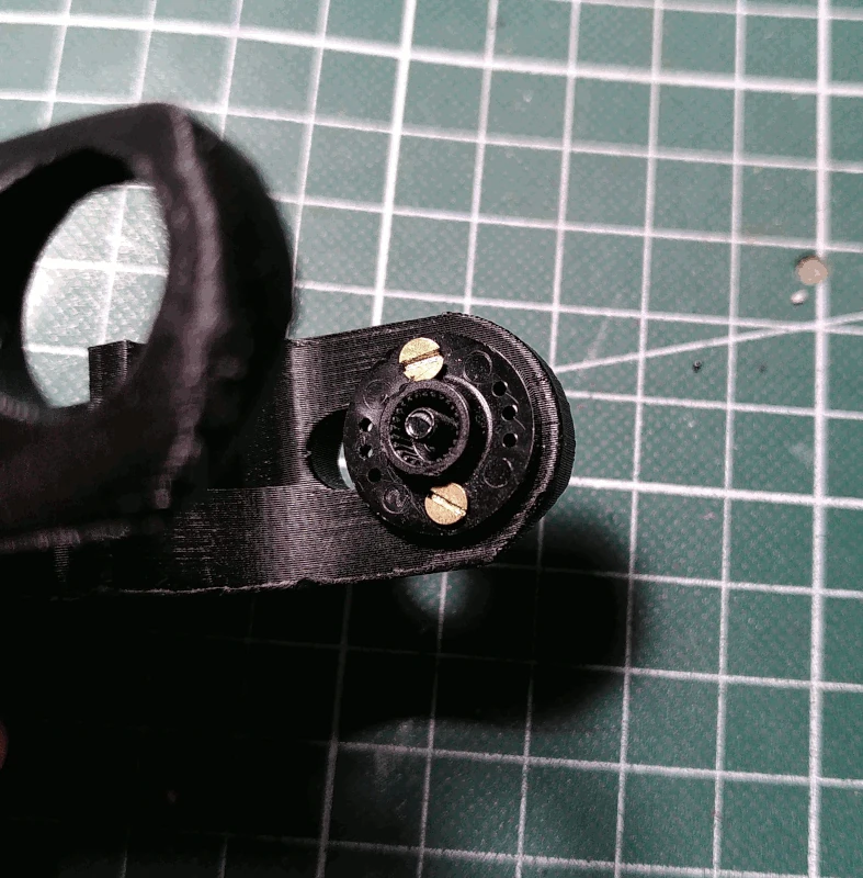
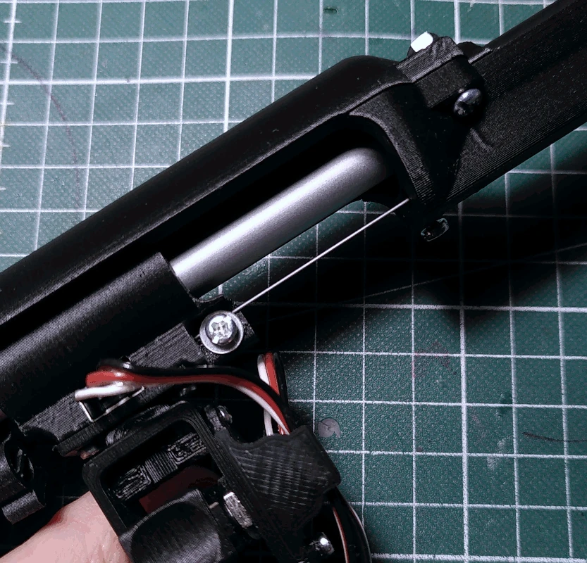
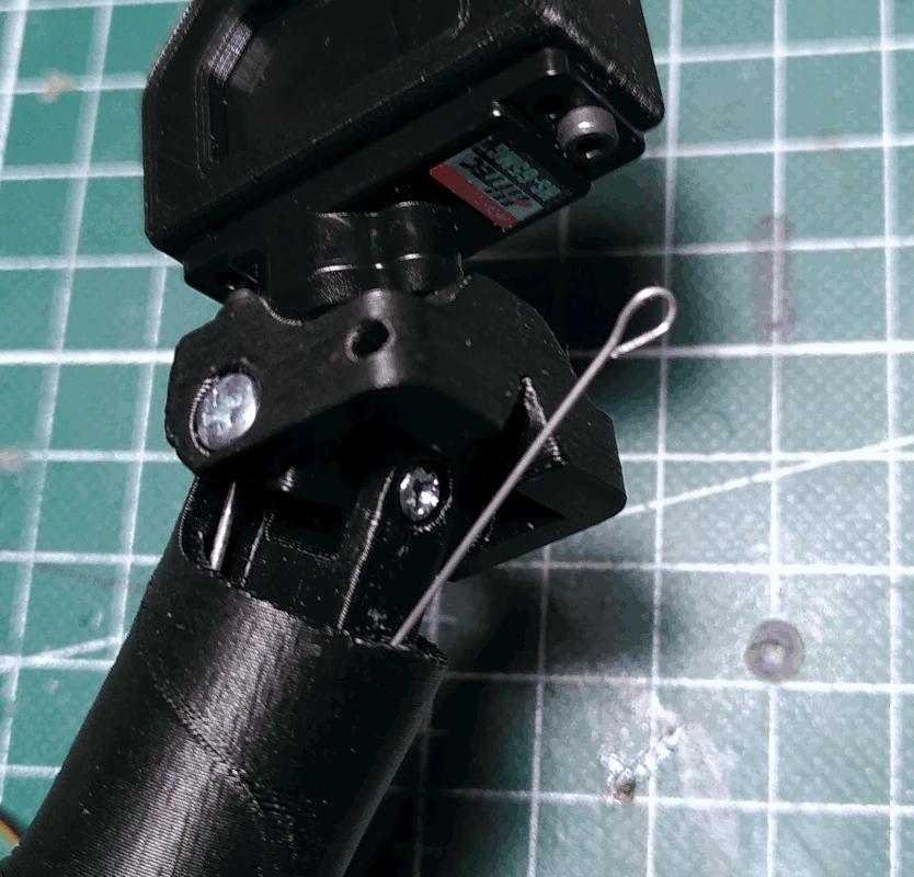
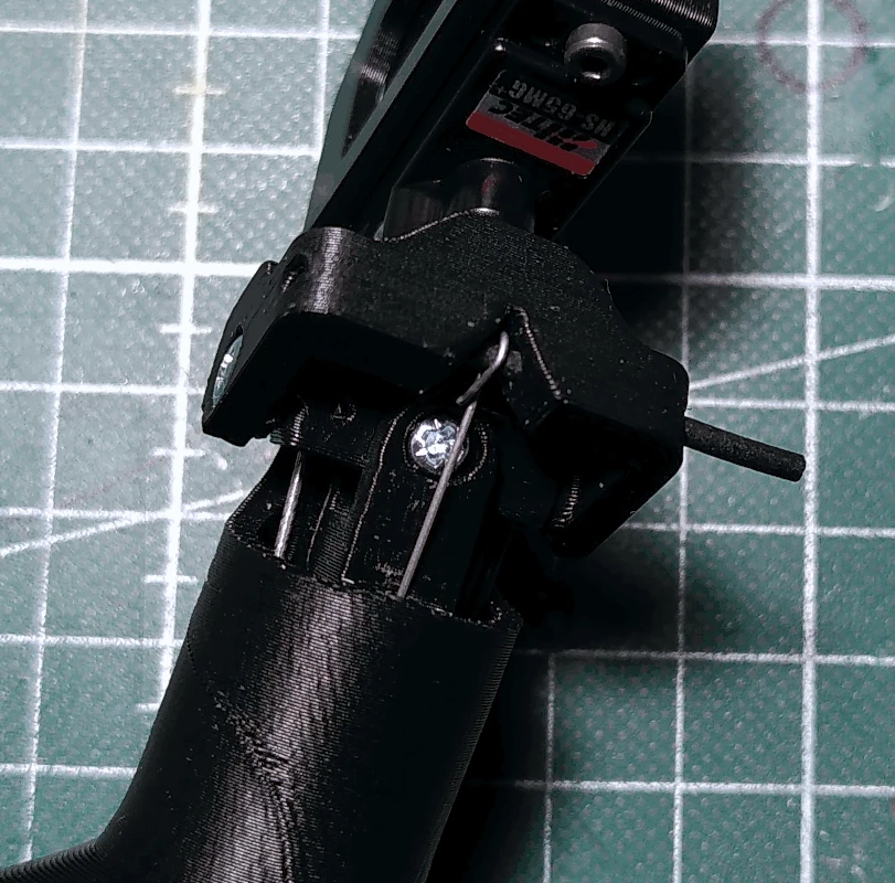
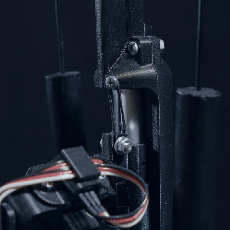
Guide the piano wire from the
handle_tube_holder into the small hole in the
bearing beneath the washer and screw, and make sure that the piano wire is between the washer and
bearing. Tighten the screw a bit so that the wire sits in place in the
bearing (there's no need to tighten it much, the length of the piano wire till be trimmed later on).
If you want to prepare the
neck (sanding etc for painting later) now is a good time to do it. After having done so, insert the PTFE tubing into its mounting hole in the
neck and, as before, make sure it is inserted all the way in. In doing so, guide the 0.5mm piano wire through the small channel in the
neck.
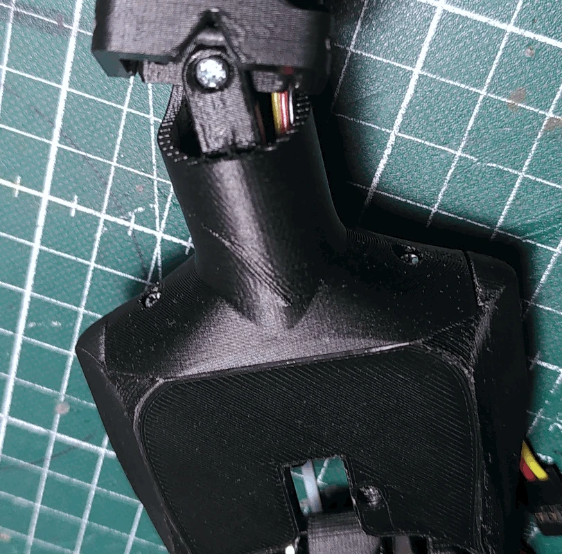
Fasten the
neck to the
torso using 2 M2x12mm screws. If you find that the PTFE tube is too long, shorten it before fastening the
neck to the
torso (first remove the tube from the
neck and loosen the 0.5mm piano wire from the
bearing and pull the wire down so that you can cut the PTFE tube).
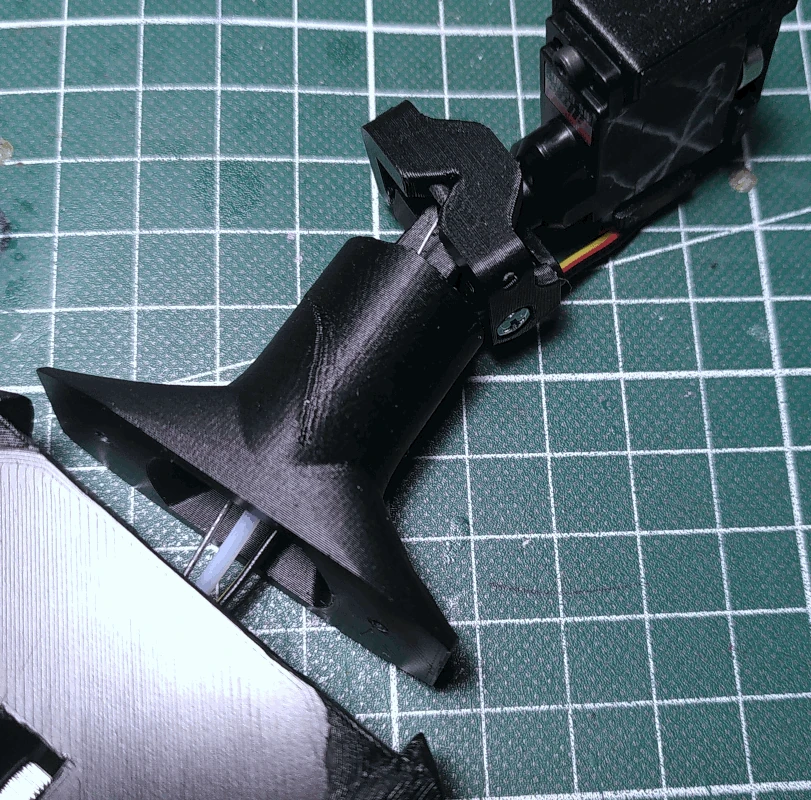
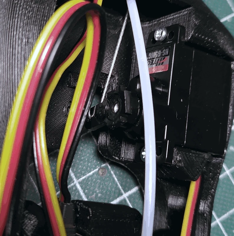
Make sure the
neck_bridge is horizontally positioned in relation to the
neck and that the servo mounted in the
torso is set to its middle position. Proceed with attaching the servo arm, hooked to the 0.8mm piano wire mounted to the
neck_bridge, to the servo and ensure that the
neck_bridge stays in position when doing so (this is to make sure that the servo middle position translates to the head being level).
Make a small eye at the end of the 0.5mm piano wire inserted through the neck. The eye should be just large enough so that a 1.75mm piece of filament can be inserted through it and rotate freely but not wiggle up and down.
Grab a small length of 1.75 filament and insert it into the small hole in the front of the
head_base and through the eye on the 0.5mm piano wire. The filament should be as long as the
head_base is wide but it is easy to trim.
The length of the 0.5mm piano wire essentially dictates the position of the
bearing as it relates to the head being moved up and down. If the wire is shortened the
bearing will be positioned higher up on the rod which is relevant to the control mechanism in terms of comfort.
If you want to shorten the wire, remove the filament keeping the wire attached to the
head_base, loosen the screw holding the wire in place on the
bearing, pull the wire up from the neck and cut it at the desired length at the end which is located down by the
bearing. After doing so, reinsert the wire into the small hole in the
bearing, fasten it using the screw and washer and reattach it to the
head_base using the filament. Depicted below is at which position I like to have my mid point set, at this position the head is looking straight forward.
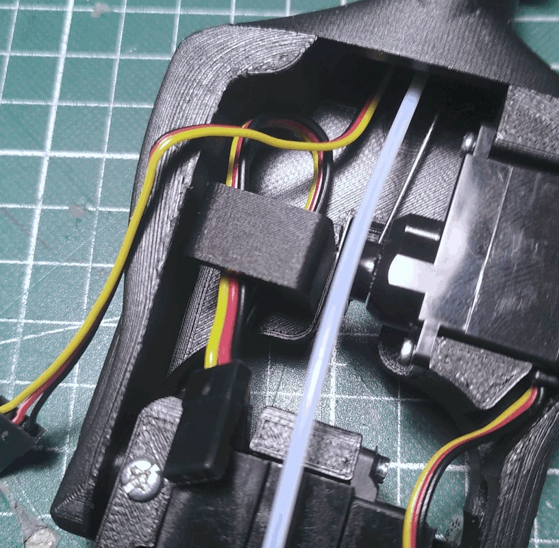
Grab the part labelled
cable_organizer and attach it to the
torso using a M2x12mm screw from the front.
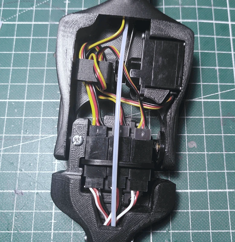
Connect the 3 servos to the wiring from the rod (it's a good idea to control which wire is which, in relation to the connectors at the bottom of the rod, using a multimeter. It's also a good idea to mark them) and organize the wires using the
cable_organizer.
Connect everything to the controller board and take note of which servo/potentiometer is connected to which channel. The inner pins along the servo rail are for the signal wire (usually yellow or white on the servo cables) and this is where the signal wires (soldered to the middle pins) from the potentiometers are connected as well. The other potentiometer wires (soldered to left and right pins) are connected to 5V+ and GND and there should be at least 2 places to connect them (since we soldered those header pins to the board earlier).
The potentiometers connected to the
front_lid share 5V+ and GND. Note that if you, like me, are using 3x1 wires the wire soldered to the middle pin of the potentiometer mounted in the
handle is likely of a different color (e.g. red and not yellow/white). If you've followed the orientation shown in the images when soldering and aligning the wires from the potentiometers mounted to the
finger_bridge and
bearing then the red wire from the
front_lid should be connected to the 5V+ and the black to GND. Switching these up simply results in the servos turning the opposite direction from that of the potentiometer shaft and should you find that this is the case with the potentiometer mounted in the
handle then just switch places for 5V+ and GND.
After connecting everything to the board, connect the wires from the 2 potentiometers mounted on the
bearing and
finger_bridge to the front lid header pins. If you've followed the recommendations regarding how to orient the wires etc the white wires from the potentiometers, soldered to different pins, will be connected to the 5V+ on the board.
Upon connecting them you may find that the header pins on the
front_lid are being pushed back instead of actually being inserted into the connectors from the wires. If you do, just use something like pliers to push them in (this is the reason for the perf board comment from earlier).
Mount the
board_holder with the board attached to it into the
housing. It's meant to just slide in there.
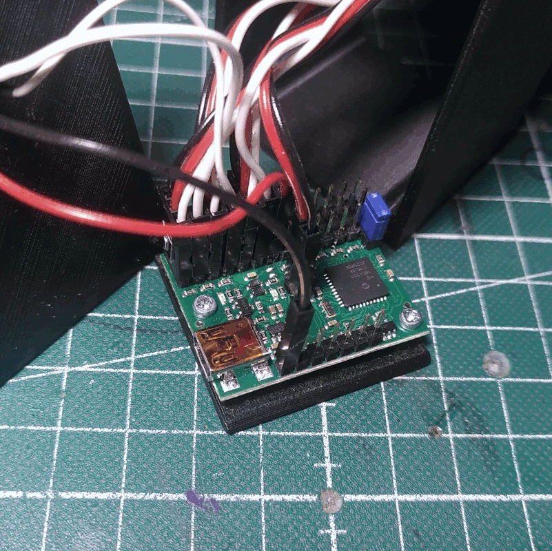
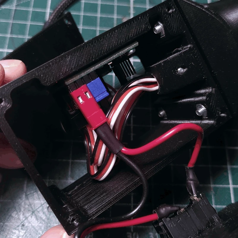
Grab the
back_lid and connect the BEC connector to the dedicated servo power pins on the controller board. Note the polarity, the 5V+ should be connected to the middle pin and GND should be connected to the outer pin.
The blue little shorting block should be disconnected at this point (it's still connected to the board in the image below for the purpose of showing it). When the shorting block is connected in the way shown below, the controller board will be powered from the same power supply as the one powering the servos. This is of course the way it will be connected later, but it's recommended to power the board via the USB cable when programming it.
Fasten the
back_lid to the
housing using 4 M2x6mm screws but there's no need to tighten them yet. After programming it will have to be removed in order to reconnect the blue shorting block to configure the board to be powered from the same power supply as the one powering the servos (it's just easier to not have the
back_lid dangling about when programming).
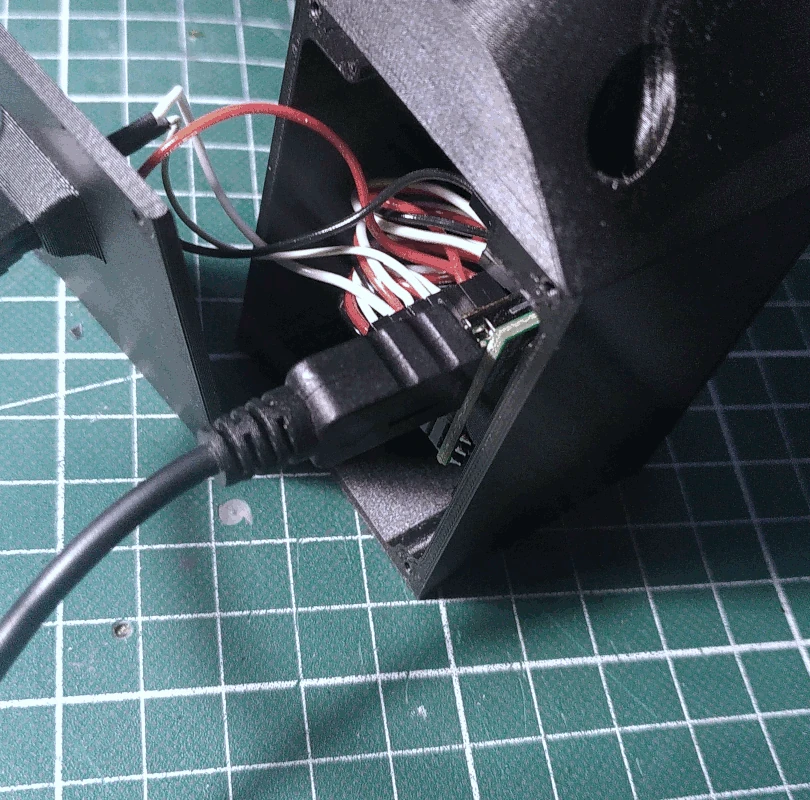
Connect a USB cable (type Micro B) to the controller board and hook it up to a computer.
Solder the GX12 connector to a 5V power supply, mind the polarity. In terms of output effect I would advise to allow for at least 1A per servo, so 3A in total, which equals a total effect of 15W (no servo is at any point under heavy load and so the average draw is likely far below the 15W mark). I normally use a 5V 10A (50W) switching power supply from MeanWell, something like
this. The total output effect is far greater than what is needed but they tend to be less expensive and more reliable than your average wall wart.
Time to program the board. If you're familiar with writing code you can probably skip the code stuff in the next section, simply check the syntax in the
documentation (the scripting language is stack-based and similar to FORTH). Do take note of the stuff about setting maximum/minimum positions for some of the servos though.
Programming the Pololu Mini Maestro is most easily done via a proprietary application called
Maestro Control Center (
Windows version and drivers). The application offers a graphical user interface with which you can configure various stuff (such as if channels are to be used for servos or as inputs/ouputs etc), position servos, make frame-by-frame animations or write scripts. Some initial setup is required before the script can be written.
After having connected the controller board to your computer, navigate to the
Channel settings tab and set the channels on which the signal wires from the potentiometers are connected to be inputs. After having done so, when a potentiometer is turned the channel slider on the
Status tab should display a value between 0 and 256 (representing 0-5V).
A standard RC servo works by reading signal pulses received on it's signal wire. The pulse width, measured in microseconds, informs it of which position it should be set to. The pulses are normally sent at a frequency of 50Hz. The default values for the minimum and maximum pulse widths in the application is 992µs to 2000µs.
However, since the ranges of some of the servos are likely to be wider than what we can allow (due to the length of the PTFE tube for example) it's a good idea to limit the allowed range for the channel on which some of the servos are connected to. Beginning with the channel on which the D89MW is connected to, simply use the slider in the
Status tab to move the servo so that the torso bends forward and gauge how far you can go before the PTFE tube is strained and take note of the value. Do the same for the backward bending motion but instead of the PTFE tube straining, simply gauge how far out you want the PTFE tube to protrude from the back when bent. After having found the maximum/minimum positions, configure these values in the
Channel settings tab.
Next, do the same for the HS-65MG/HB servo mounted in the
torso (which accounts for the head tilting motion). The range of the tilting motion is narrower than the range of the servo motion which results in the 0.8 piano wire bending when pushed too far upwards (that is, when the head is tilting to the left when facing towards you). In the other direction the wire will be pulled downwards more than the
neck_bridge can move. As with the D89MW servo, gauge how far the head can tilt in each direction based on the 0.8mm piano wire and set the maximum/minimum positions accordingly.
After having set the minimum/maximum allowed positions for servos we can proceed with writing the script. The syntax for the Pololu Mini Maestro is simple, below is an example of what code is required in order for a potentiometer to control the position of a servo (taken from the
documentation):
# Sets servo 0 to a position based on an analog input.
begin
1 get_position # get the value of the pot on channel 1, 0-1023
4 times 4000 plus # scale it to 4000-8092, approximately 1-2 ms
0 servo # set servo 0 based to the value
repeat
As can be observed in the example given above, all that is needed is to read the input value of a channel with
channel number get_position (received as a value of 0-1023), convert it to a pulse width (where the value 4000 roughly corresponds to 1 millisecond, or 1000 microseconds) and to set the position of a servo on some channel to the converted value. Simply create 3 of these 3-step blocks, one for each input/servo pair, within the
begin and
repeat lines.
Since you might not want to map the full range of the servo motion to the full range of the potentiometer but instead have the servo rotate more than by how much you are turning the potentiometer, the best way to to go about it is simply to experiment with different conversion values until you find something that results in smooth movement and comfortable controlling.
Example code of the full range of a HS-65MG/HB servo mapped to a portion of the input value range from a potentiometer:
begin
1 get_position
400 minus
25 times
4000 plus
0 servo
repeat
The above example maps the full range of the servo to the input value range ~400-560 (~100-142µs when viewed in the
Status tab). It works in the following way: an input value is read from a pot on channel 1. Then the value 400 (the starting point of our narrowed down input range) is added to the stack. Next (the line with 'minus') the value 400 is subtracted from the previously received input value. The resulting value is then multiplied by 25 and then scaled (by adding 4000) before being sent to the servo on channel 0. The code is based on the following equation:
8000 = (560 - 400) × 25 + 4000
The equation can be used to calculate the correct multiplier for any input range by letting the multiplier (25 in the above given example) be
x and using whatever maximum and minimum input values in the desired range.
A common issue when working with RC servos is servo jitter, caused by noise on the signal line from which the servo position is calculated (it may also be a result of faulty connections or an unstable power supply). There are essentially two ways to mitigate a noisy signal line, either in hardware or in software.
The hardware route consists of implementing a passive RC low pass filter. Only two components are required, a resistor and a capacitor (hence the RC in the name). The filter works in such a way as to limit the frequency of the signal passed through to an extent determined by the frequency cutoff. The frequency cutoff is determined by the values of the resistor and capacitor used and can be calculated using the following formula (there are calculators available online to do the work for you): FC = 1/(2πRC).
To mitigate servo jitter in software a common approach is to perform multiple readings of a signal, calculating an average value and using the resultant value to inform the servo position. This is an easy approach and doesn't require any additional hardware. Building on the example shown above such an implementation might look like this:
begin
1 get_position
9 begin dup while swap
1 get_position plus
swap 1 minus
repeat
drop
10 divide
400 minus
25 times
4000 plus
0 servo
repeat
In the example above the signal value from the potentiometer is read 10 times after which the average value of the readings is then used to calculate the servo position. In theory it would be possible to perform more than 10 readings, thus increasing accuracy, however since this operation is being performed in relation to controlling 3 servos there's a risk that the added computational overhead starts to affect the smoothness of motion. Taking 10 readings per signal does not seem to have a detrimental effect on the motion and should suffice for the purposes of elimating noise on the signal line to a reasonable degree (if not you might want to do some troubleshooting or simply switch out the potentiometer).
After having written the script, make sure to tick the
Run script at startup option in the
Script tab, click
Apply changes, turn the power off and disconnect the controller board from your computer. Remove the
back_lid and reconnect the blue shorting block, enabling the board to be powered from the main power supply. It's a good idea to verify that the script runs on startup and that everything checks out, simply turn the power back on and check how everything is working. If everything is working as intended, attach the
front_lid and re-attach the
back_lid using 4 M2x6mm screws for each.
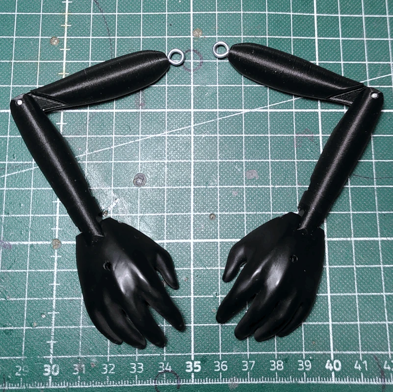
Now the main body of the puppet is built and programmed and it's time to move on to the arms, legs and head. It's of course entirely possible to ditch the arms and legs included in the parts archive and make your own, these parts do not figure into the design in any mechanical sense (with the exception of how the head fits into the
headservo_holder). They are pretty generic and are included for the sake of including a complete puppet.
Grab the part labelled
wrist_right and, using glue, attach a short length of filament to the ridge. Cut the length of filament so that it protrudes around 3mm from the bottom of the
wrist_right. There is an alternative wrist part included in the archive named
wrist_nostop on which there is no protruding edge to limit for how far the hand can rotate, to be used if you want to set your own limit.
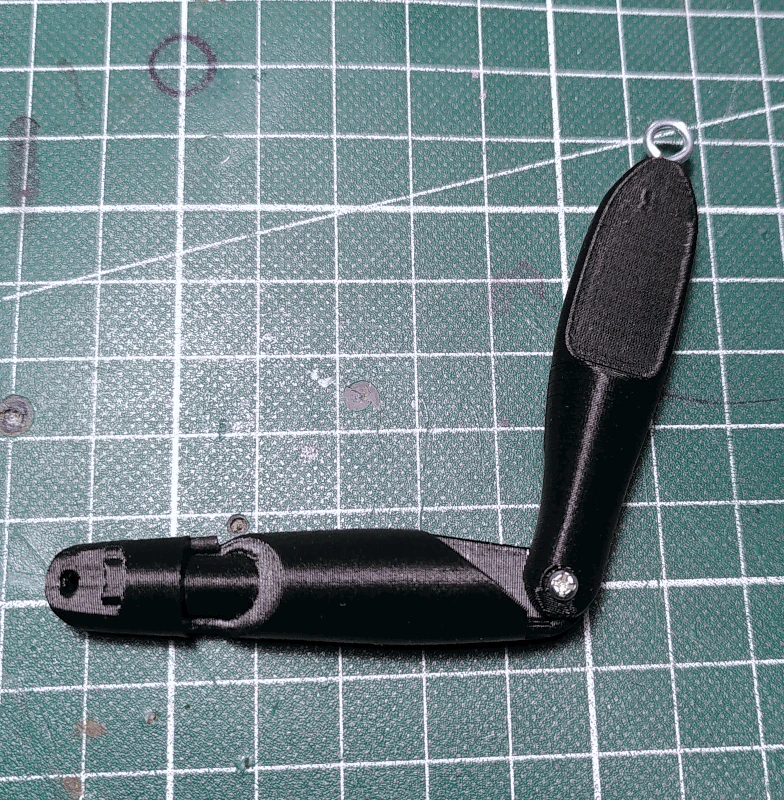
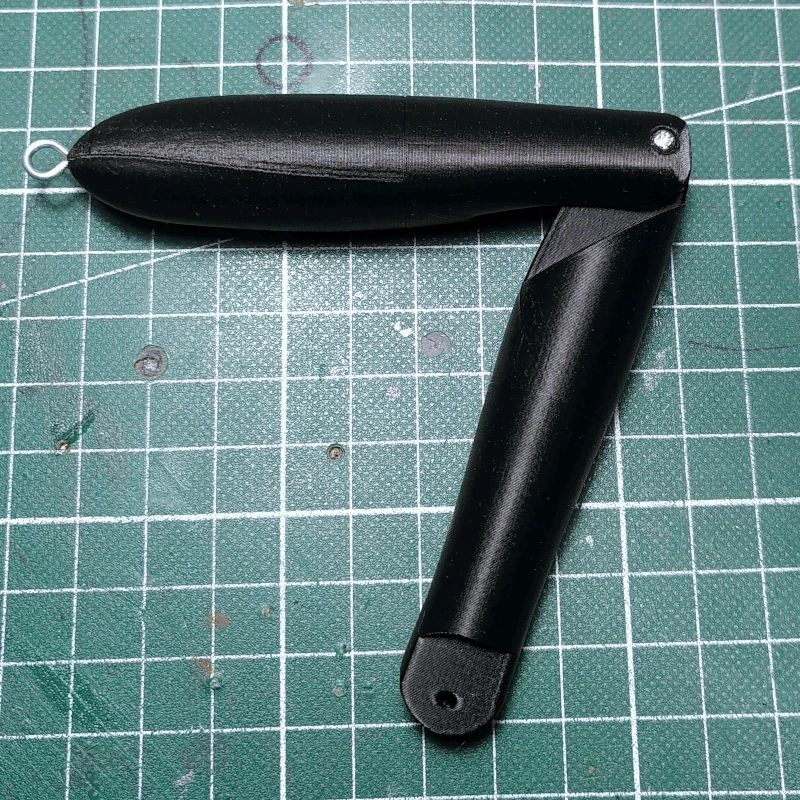
Fasten the
wrist_right to the part labelled
arm_lower_right using a M2x12mm screw. Tighten it just enough so that it can spin freely without wobbling. If you find it hard to get a M2x12mm screw through the
wrist_right it might be
easier to use a M2x19mm screw instead.
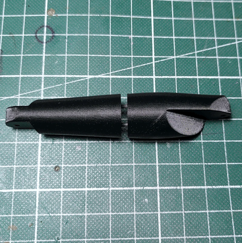
Grab the part labelled
arm_upper_right_1 and cut two pieces of filament ca 1cm in length. Insert the filament pieces into the two holes in the bottom of the
arm_upper_right_1.
Attach the part labelled
arm_upper_right_2 to the
arm_upper_right_1 using glue. There are holes on the
arm_upper_right_2 as well and the pieces of filament will ensure a perfect fit.
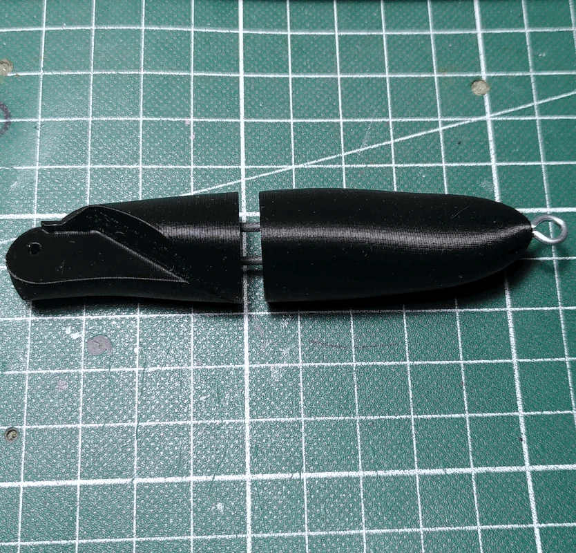
Attach the assembled lower arm to the assembled upper arm using a M2x12mm screw, tighten it just enough so that the lower arm can rotate freely without wobbling. Fasten a 6x3.5mm eyebolt screw to the top of the
arm_upper_right_1.
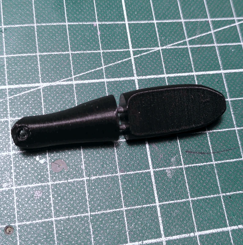
Grab the part labelled
hand_right_*. There are two variations of this part and of each variation there are two versions, of which one is split into two separate pieces,
hand_right_lower_* and
hand_right_upper_*. The split version is meant to be printed with an FDM printer and the other version is meant to be printed with a resin printer. When printing this kind of part with an FDM printer I find it easier to do it in two separate parts and then glue them together (allowing for a little bit of elephant foot makes the assembly easier) instead of using supports. The two different variations of the part differ in terms of design. One is designed for the control rod to be mounted on the outside of the hand, labelled
hand_right/left_outer_rod and the other is designed for the rod be mounted on the inside, labelled
hand_right/left_inner_rod.
It may be difficult at this stage to know which one works best for you, you'll simply have to try both in order to find out. I prefer to have the rod mounted on the outside of the hand and don't mind that it's more visible this way. The image below to the left depicts the
hand_right_outer_rod printed using a resin printer.
The hand is attached in the following way, however it's likely better to wait with actually doing so until the control rods have been prepared and the hands are attached to them: Attach the
hand_right to the
wrist_right using a short length of filament. It normally does not have to be glued but note that if you do secure it with glue and should want to replace it, the it's likely that the whole lower arm has to be replaced as well.
Now do the same for the left arm, where parts are labelled
wrist_left etc.
Grab the parts labelled
leg_right_lower_1 and
leg_right_lower_2 and glue them together in the same vein as before, by using two short lengths of filament. Do the same for the parts labelled
leg_right_upper_1 and
leg_right_upper_2 and fasten a 6x3.5mm eyebolt screw to the top of the assembled upper right leg.
Just as before with the arm, attach the assembled lower right leg to the assembled upper right leg using an M2x12mm screw.
Attach the part labelled
foot_right to the
leg_right_lower_2 using a short length of filament, in the same vein as was done with the hand.
Repeat the process for the other leg. There are no holes for any rods in the feet parts however it should be trivial to add should you desire to do so.
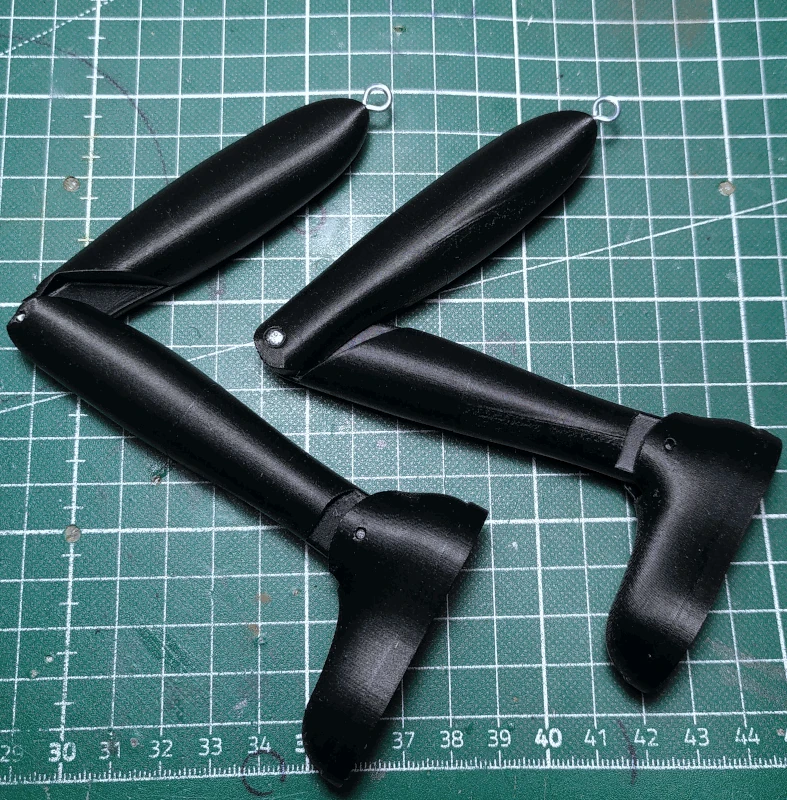
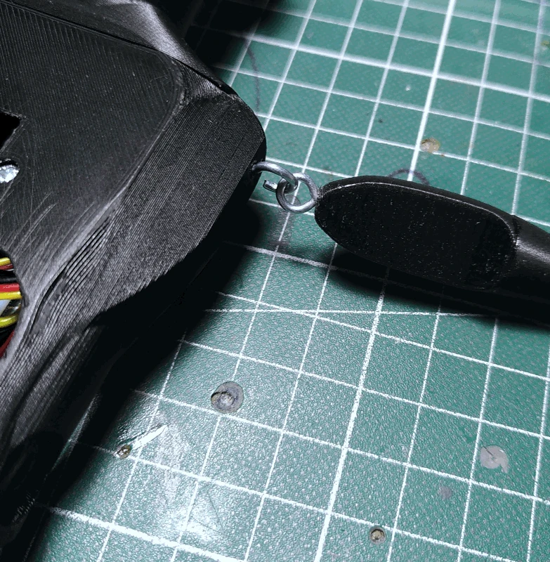
Attach 4 6x3.5mm eyebolt screws on the
hip and
torso.
Attach each arm/leg by bending one of the eyes on the screws and hooking the eye on the other part on it.
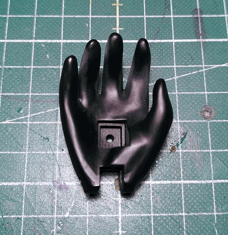
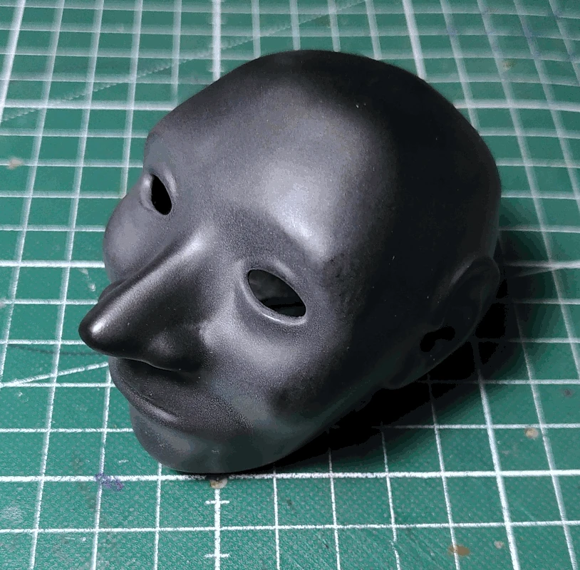
Grab the part labelled
head (similar to the hand parts there are two versions of the
head, one which is split into two separate parts for FDM printers and one which is not, for resin printers. The image below depicts a head printed using a resin printer).
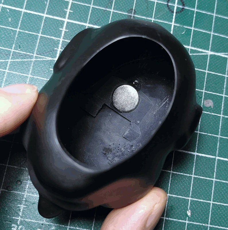
Grab the other 12x3 neodymium magnet and secure it to the socket for it inside the
head using a strong glue. Mind the polarity! If the magnet is glued to the
head the wrong way it won't mount to the assembled neck properly, it's a good idea to first check which side of the magnet that should be facing downward by simply snapping the magnet unto the
headservo_holder and marking one of the sides.
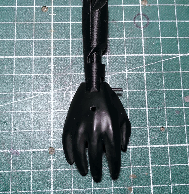
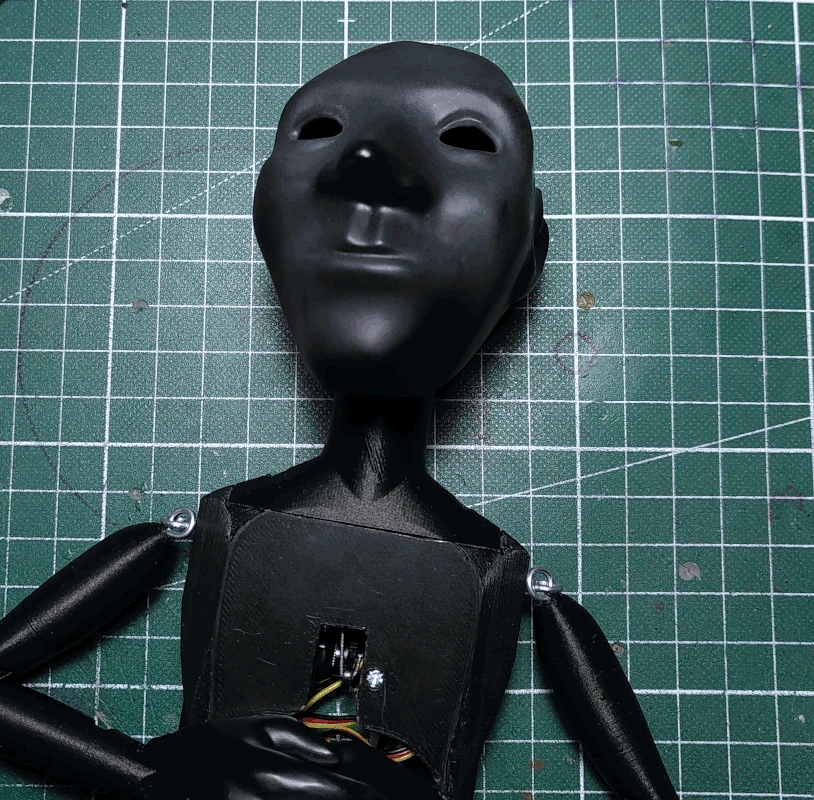
The
head is mounted unto the body by simply inserting the assembled neck into it. It should just snap into place. If it doesn't, try to rotate it so that the
headservo_holder falls into place. You know that it has done so when you can't rotate the head from side to side without also rotating the servo itself (something that is not recommended to do, it's never a good idea to backdrive a servo).
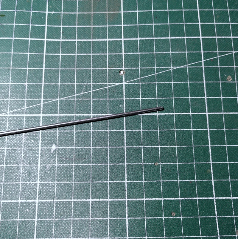
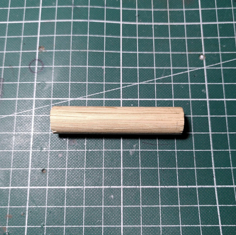
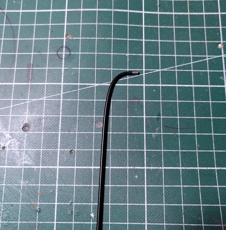
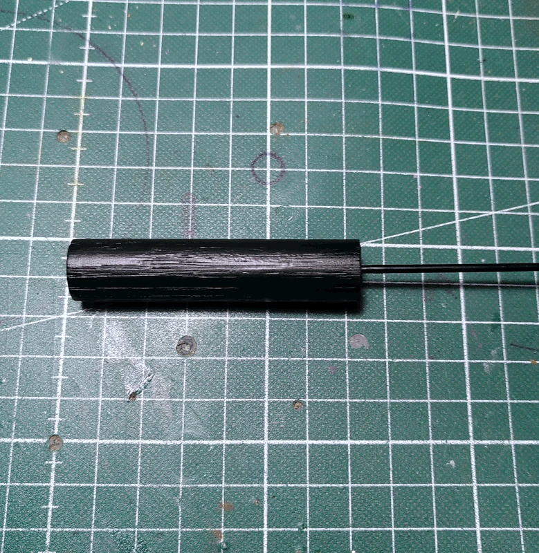
Cut the 2mm steel rod into 2 pieces around 35cm in length (or any length you like).
Cut the 15mm wooden rod into 2 pieces around 8-10cm (or any length you like).
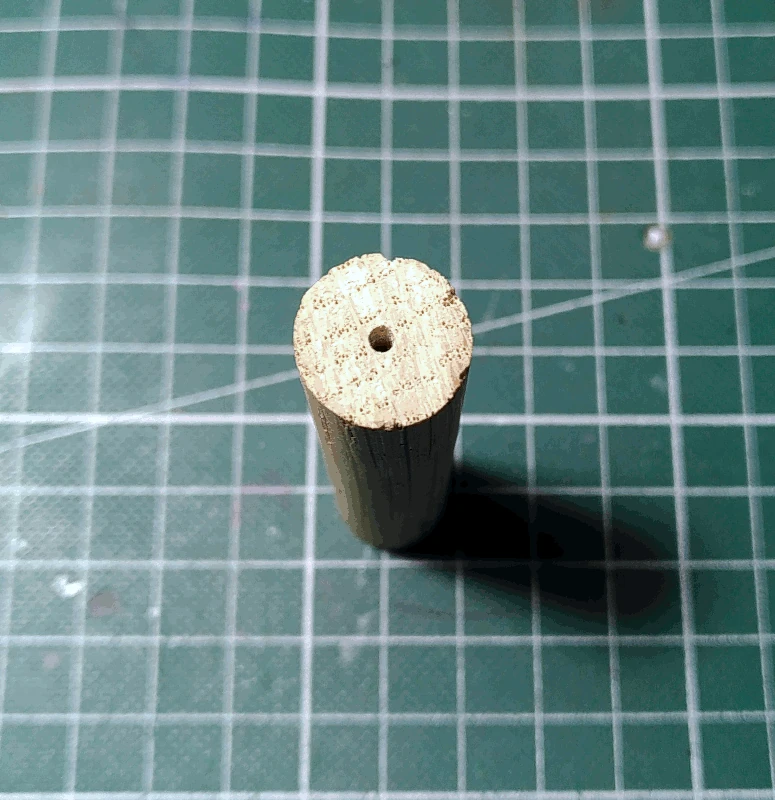
Drill a 2mm hole around 1-2cm deep in wooden rod pieces. It's common for the hole to be off center but I prefer having the rods centered in the handle. Do you as you please.
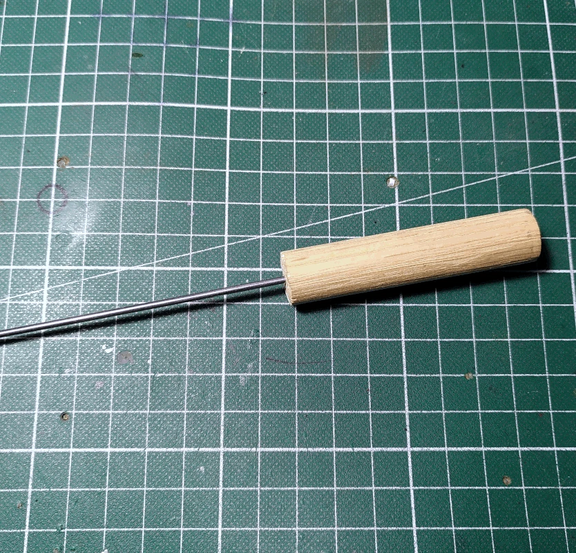
Insert the steel rods into the wooden rods. If they need to be glued to stay in place, do so.
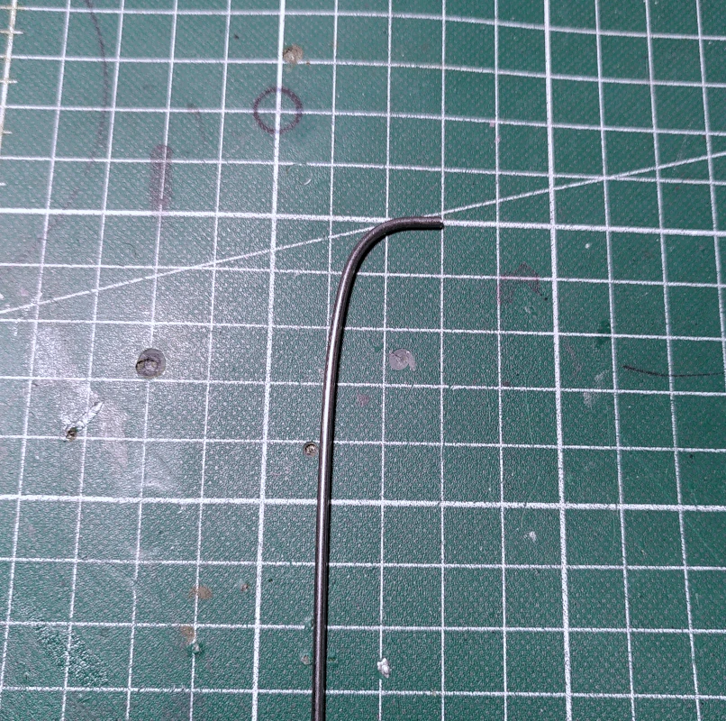
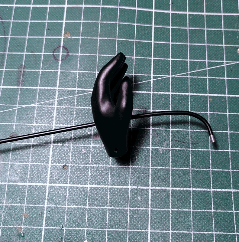
Bend the ends of the steel rods. If you're using the hands that are included in the parts archive it's a good idea to bend them in such a way as can be observed in the image below to the right.
If you want to paint the rods now is a good time (I usually spray paint them black) but leave around 2-3mm unpainted on the ends of the ends that are bent.
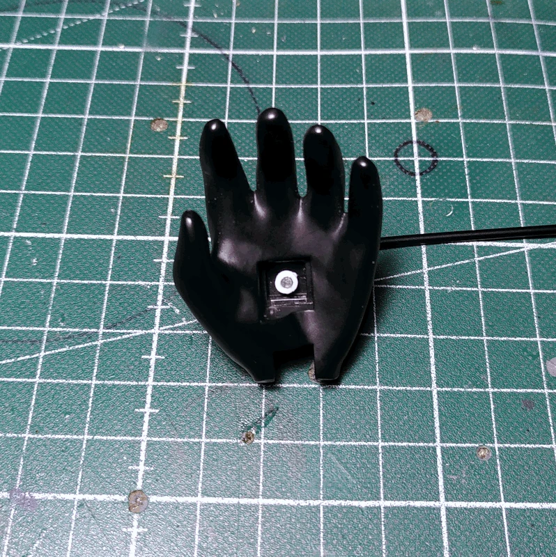
Insert the steel rod through the hole in the hand (orientation as depicted below). If you're having difficulties doing so the bend radius is likely too tight.
In these instructions the hands for having the control rods mounted on the outer sides are used but if you're using the hand parts to which the control rods are to be mounted on the inner side, the assembly is principally the same. If you review the following steps if should be very easy to understand how the assembly differs.
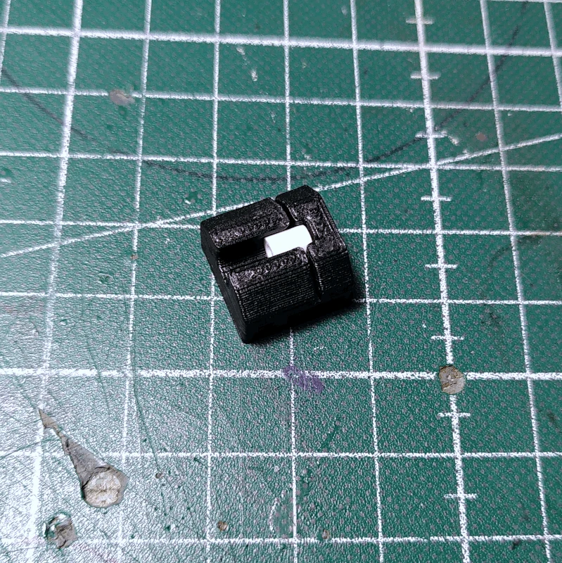
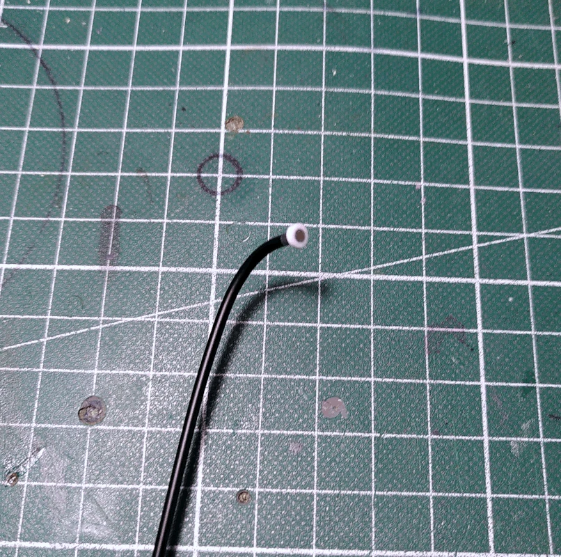
Cut the 2mm ID plastic distances into shorter lengths, around 2mm. This can be a bit difficult and if you plan on constructing more than one puppet it's a good idea to use the part labelled
cut_help to aid in the cutting.
While keeping the hand a bit further down the rod, glue the piece of the plastic distance to the tip of the steel rod and let it dry.
After having made sure the glue is dry at the end of the rod, guide the hand back up to the end of the rod.
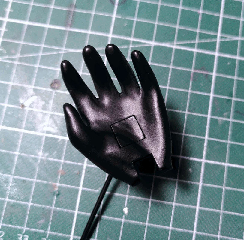
Attach the part labelled
hand_right/left_cap_outer_rod (if mounting the rod to the inner side of the hand the rod will be inserted into this part instead. The cap for inner rod mounting has a hole in it instead of the hand), preferrably using small
pieces of thin double sided tape. It's of course possible to use glue instead but should the plastic distance come loose from the end of the rod it will be very hard to repair it without making a new hand. If the double sided tape is strong it will likely hold even with heavy usage while still being removable with enough force.
Re-attach the hands to the arms of the puppet and do a final check so that everything is working as expected.
If you find the head to be too heavy to move up and down it's recommended to attach a rubber band as depicted below, using the M2.5mm screw on the
handle_tube_holder and the M3 screw keeping the 0.5mm piano wire attached to the
bearing. Secure the lower end of the rubber band to the M3 screw on the
bearing using a washer and an M3 nut.
There's a part labelled
base included in the archive, the purpose of which is to increase the stability when the puppet is standing (for example when used in film making as opposed to live performances). It detaches easily and can be used as a stand in general as well.
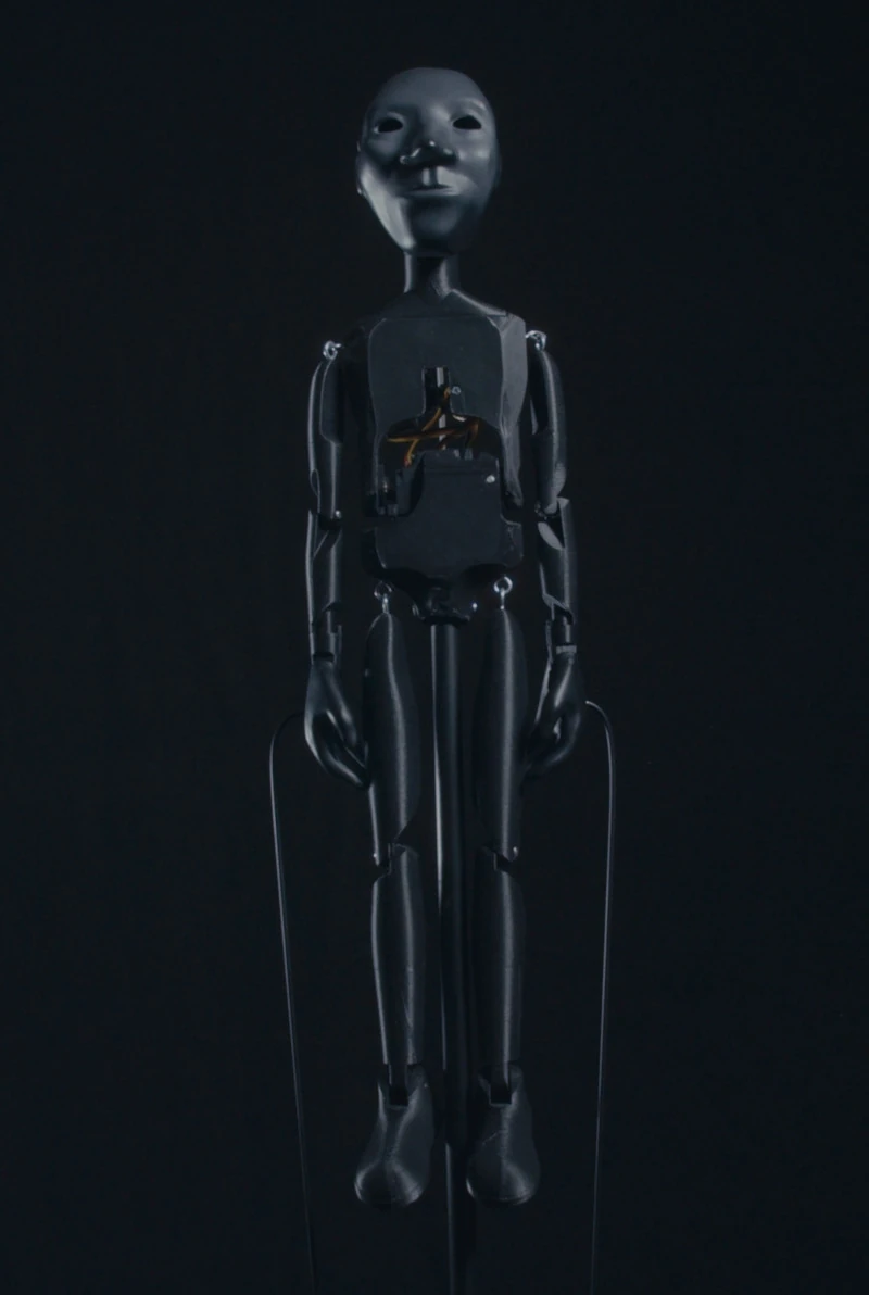
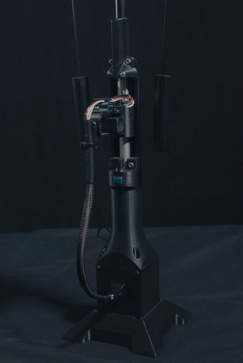
The puppet is now finished and the controller and puppet should look something like the images below. All that remains now is to do some painting, learn how to make tiny clothes and practice.
Enjoy!